Pag. 37
Technical
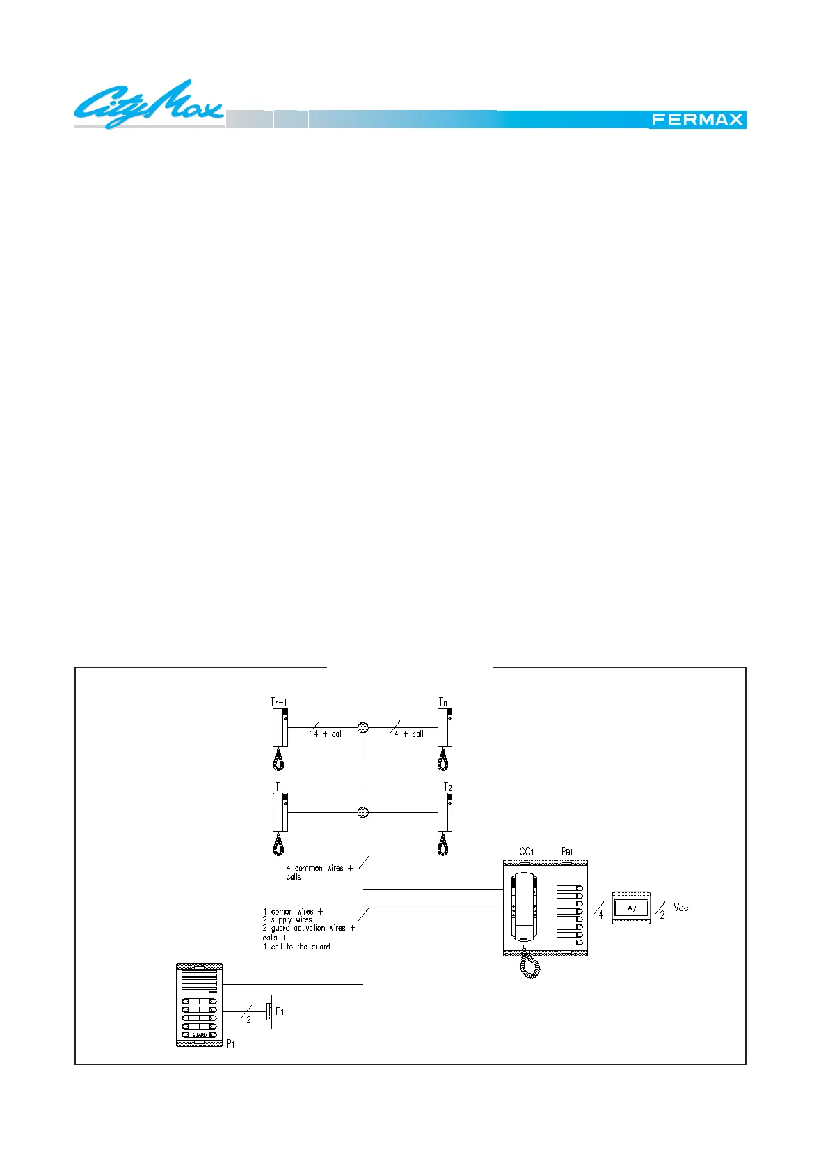
Door phone diagram with a CityCom III basic Guard Unit.
SCHEMATIC DIAGRAM
BASIC FUNCTION
The CityCom III Guard Unit consists of a special guard's
phone and a panel with the same number of pushbuttons
as the outdoor panel. In fact, each pushbutton on the guard
unit corresponds to a button on the outdoor panel, (see
diagram).
It has a key to activate and disactivate it.
When it is on ("day mode") the calls made from the outdoor
panel are passed through the concierge, who can then
transfer them to the dwelling called.The residents can call
the concierge by picking up the phone and pressing the
door release button, which produces an audible signal in
the guard unit. The concierge can speak to the resident by
simply picking up his receiver.
When it is off ("night mode") the calls made from the outdoor
panel are sent directly to the telephone called, the system
working in the normal way. From the guard unit it is not
possible to receive or make calls to the dwellings.
The CityCom III Guard Unit features other functioning
modes, which can be configured with the bridges
CN5-CN8.
See the installation manual with the Guard Unit.
MATERIALS USED
In the dwellings
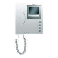
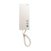
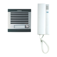
T1,T2,...Tn CityMax Telephones Ref.: 8044
In the communal interior area
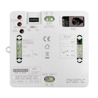
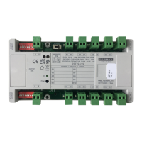
A7 Distributor Power Supply Ref.: 88231
CC1 Guard Unit Ref.: 84601
PB1 Basic Pushbutton Panel
Combination neccessary. The number of pushbuttons
signal in the Guard Unit has to coincide with those on the
outdoor panel.
In the street
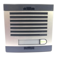
P1 Outdoor Panels
Combination neccessary.
F1 Electrick lock Ref.: 2911
For other types consult catalogue.
E 1.8 DOOR PHONE SYSTEM
CITYCOM III. BASIC VERSION