Pag. 58
Technical
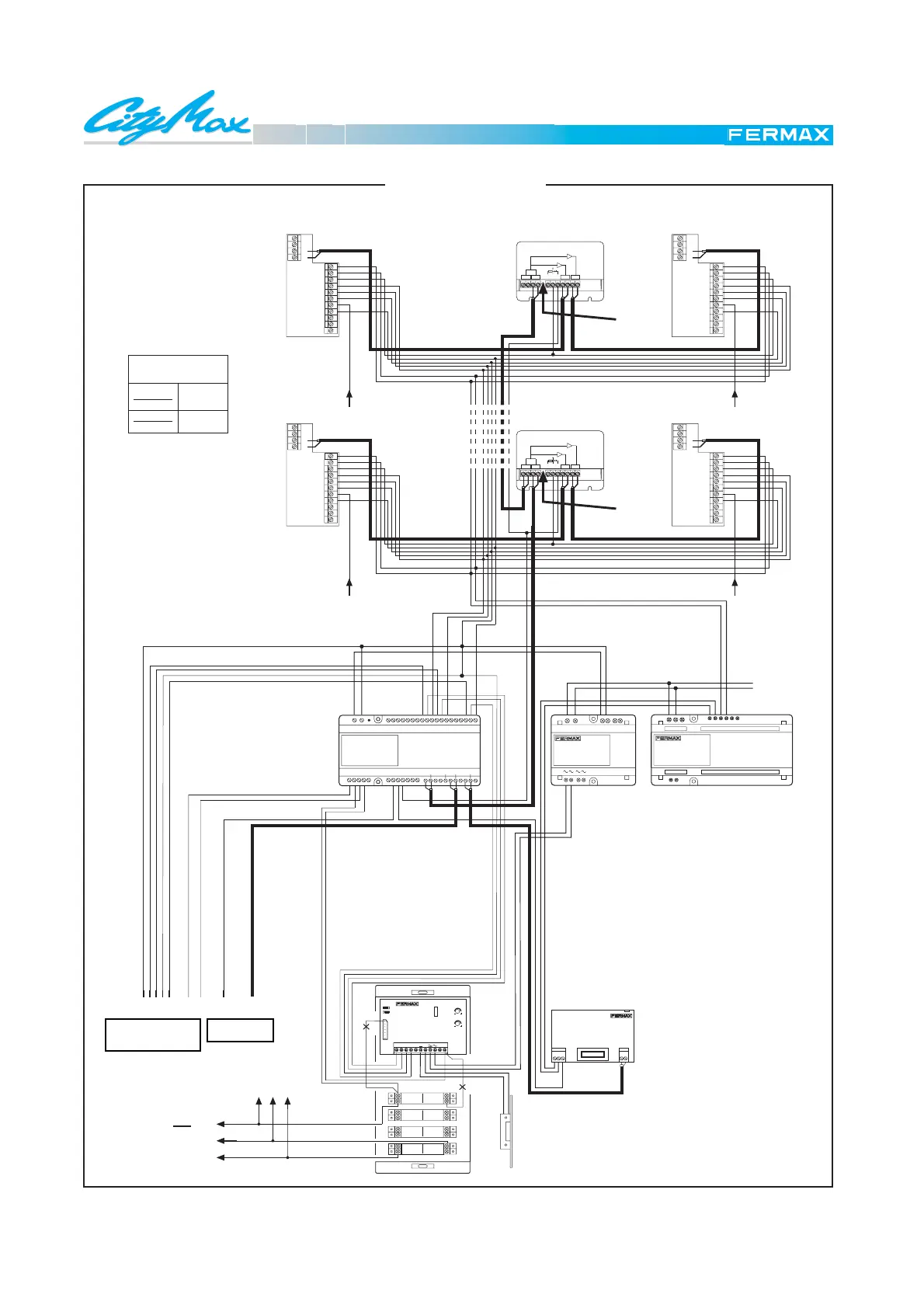
WIRING DIAGRAM
LAST BLOCK
E 2.5 VIDEO PHONE SYSTEM
CONDOMINIUM WITH SEVERAL BLOCKS
M
1
M
n-1
M
M
2
n
2.n
D
2.1
D
F
1236
H
Vac
FE
-+-+-+
-
COAX
CT
J
33
3
A
A
7
3
A
6
-+CT VM
HI J FALK BCDE G SV SV E1 E2
-+5M
12 436OQPR UST VW ZYX
PRIM SEC. 18Vdc220V
-+-
PRIM
+
4
6
7
E
+S
-
2
3
CT
1
+S
M
V
V
M
+
M
V
V
M
3
E
7
6
4
2
+
-
CT
1
4
6
7
E
+S
-
CT
1
2
3
M
V
V
M
+
4
6
7
E
+S
-
CT
1
2
3
M
V
V
M
+
+18
2 OUTPUTS VIDEO DISTRIBUTOR
2 OUTPUTS VIDEO DISTRIBUTOR
+18
15
VV M
75
M
R1
REF.2448
V
5
V
1
M
75
M
R1
REF.2448
62
34
V MVM
+
34
+
V
2
MV
6
M
21
n-1n
DISTRIBUIDOR VIDEO 2 SALIDAS
DISTRIBUIDOR VIDEO 2 SALIDAS
CONECTOR TEST
DE PRUEBAS
CN1
EXT.
INT.
3
PT1
PT2
1
2
FU
1
3
2
6
Ab
Cp2
Ab
Cp1
Tc
SECTION TABLE
Distances
up to 300 meters
0.5 mm
1 mm
2
2
Call
Call
CallCall
To the General
Entrance
Diagram
To the call
terminal (4)
of each
telephone.
DON'T CUT RESISTOR
CUT
(*)
(*) Cut the common pushbutton wire (according to the panel model).
CUT
(*)
CUT RESISTOR
TO THE GENERAL
ENTRANCE DIAGRAM
TO BLOCK 2
DIAGRAM
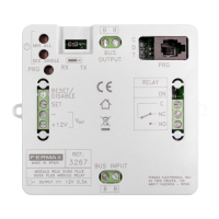
UNIVERSAL
AMPLIFIER
CALLS