Pag 12
Kit Halo & iLoftKit Halo & iLoft
Kit Halo & iLoftKit Halo & iLoft
Kit Halo & iLoft
Kit Halo & iLoftKit Halo & iLoft
Kit Halo & iLoftKit Halo & iLoft
Kit Halo & iLoft
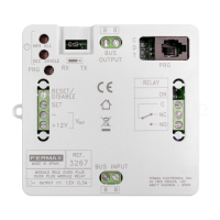
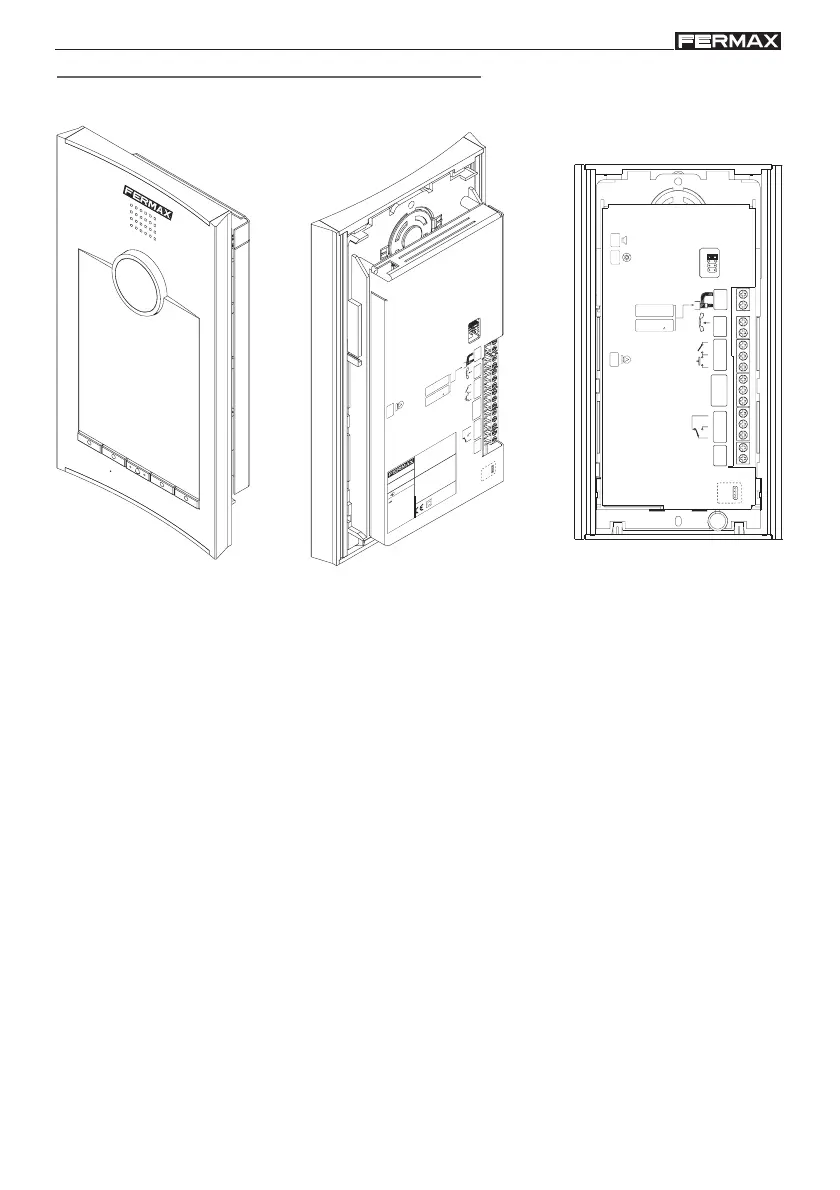
• CN1: Loudspeaker connection.
• CN2: PC Connection (by means of decoder programmer).
• CN3: Remote camera heat resistance connection.
• CN4: Microphone connection.
• CN5: Backlit functions keypad (5 keys) connection.
• CN6: Remote camera-light circuit connection.
• CN7: Video terminals (coaxial).
- V: live
- M: shield
• CN8: Proximity antenna connector.
• CN9: System connection terminals:
- “+, -”: power supply (18 Vdc).
- C, NA, NC: relay contacts (door-opener connection).
- “+12”: 12 Vdc
- Sa, Sb: connection to clone panels
- BS, -: exit pushbutton from the hall.
- SP, - : door-open sensor.
- S: activation of the switcher.
- L: data bus.
• CN10: Programming connector.
• CN11: Backlit alphanumerical keypad (12 keys) connection.
• CN12: Temperature sensor connection.
ALT CAM
MIC
M
V
L
S
A
B
D
C
VÍDEO COMPUESTO
COMPOSED VIDEO
1 Vpp. 75
CCIR 50 Hz
IDIOMA
LANGUAGE
SP
-
BS
NC
+12
Sa
Sb
NA
C
-
+
18Vdc
SENSOR TEMP.
M
V
L
S
SP
-
BS
NC
+12
Sa
Sb
NA
C
-
+
V
ÍD
E
O
C
O
M
PU
E
S
T
O
C
O
M
PO
S
E
D
V
ID
E
O
1 V
pp. 75
C
C
IR
50
H
z
1
8
V
d
c
A
B
D
C
ID
IO
M
A
L
A
N
G
U
A
G
E
1
8
V
M
A
D
E
I
N
S
P
A
I
N
REF. 5700
INPUT
M
I
C
S
E
N
S
O
R
T
E
M
P
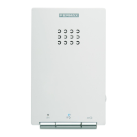
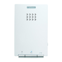
Halo panel connectors