Pag 13
Kit Halo & iLoftKit Halo & iLoft
Kit Halo & iLoftKit Halo & iLoft
Kit Halo & iLoft
Kit Halo & iLoftKit Halo & iLoft
Kit Halo & iLoftKit Halo & iLoft
Kit Halo & iLoft
PROG
.
T
A+
-
LVF2
+
Ct MF1 V
Ct + MVMVF1
T
A+ L-F2
PROG.
SW3
SW5
SW4SW2
SW1
NOK
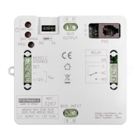
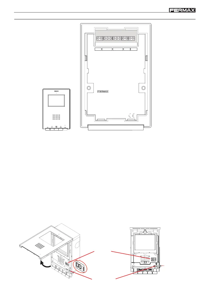
Monitor Conectors:
• Video terminals (coaxial):
V: live
M: shield
Ct: camera activation (10 Vdc)
• Connection Terminals:
+, -: 18 Vdc power supply).
L: data bus.
F1, F2: additional functions (negative output «-»).
T, -: Call Button Connection for Door of Residence
A, +: Call extension connection ref. 2040, light and bell activator ref. 2438, etc...
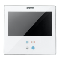
Programming display: shows the ADS call number programmed.
PRG button: button to go into programming mode.
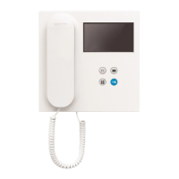
Display
PRG button
Press to go into
programming
mode
ILOFT MONITOR DESCRIPTION