Pag 15
Kit Halo & iLoftKit Halo & iLoft
Kit Halo & iLoftKit Halo & iLoft
Kit Halo & iLoft
Kit Halo & iLoftKit Halo & iLoft
Kit Halo & iLoftKit Halo & iLoft
Kit Halo & iLoft
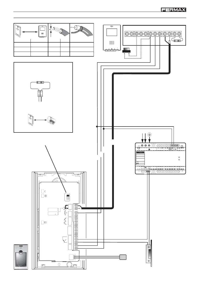
Temperature
sensor
WIRING DIAGRAM
+
-
L
COAX
Ct + MVMVF1
T
AL-F2
75 Ohm
230V
~
~
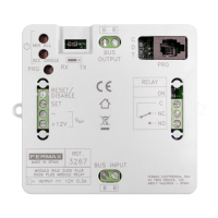
INPUT
230V ; 0,6 A
50-60 Hz
OUTPUT
18 V ; 1,5 A
~
OVERLOAD
ON
~~
~
12 V ; 1,5 A
V
ac
12 V
ac
ALT CAM
MIC
M
V
L
S
A
B
D
C
VÍDEO COMPUESTO
COMPOSED VIDEO
1 Vpp. 75
CCIR 50 Hz
IDIOMA
LANGUAGE
SP
-
BS
NC
+12
Sa
Sb
NA
C
-
+
18Vdc
SENSOR TEMP.
18Vdc + 12 Vac
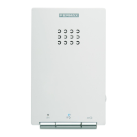
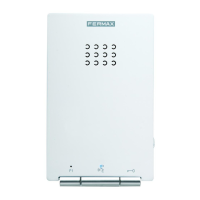
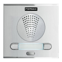
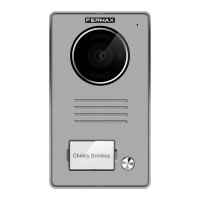
TOP PERFORMANCE PANEL
ACCESS CONTROL SYSTEM
12 Vac
18Vdc
P1
1 - 50
50 - 100
100 - 200
75 Ohm
75 Ohm
75 Ohm
mm
mm
mm2,5
1,5
1
2
2
2
S
D
metros / metres
pies / feet
AWG
3,28 - 164,04
164,04 - 328,08
328,08 - 656,16
mm
2
17
15
13
Place a 10 Kohm resistance between
the + and L monitor terminals..
(*) IMPORTANT
10 Kohm
+ L
+
1
8
V
1
.
5
A
5
0
-
6
0
H
z
.
5
0
V
A
M
A
X
.
1
2
V
1
A
F
UE
NT
E ALIME
NTA
CIO
N
K
I
T
D
IG
I
T
A
L
M
A
D
E
I
N
S
P
A
I
N
D. max.
30 m
90 pies/feet
Voice synthesis
A- Español
B- Francais
C- English
D- Deutsch
P1: House number call button.