20
EN
cod. 3540S123 - 07/2010 (Rev. 00)
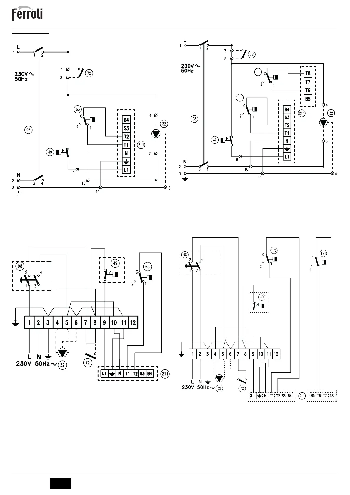
5.4 Wiring diagram
Main wiring diagram ATLAS 32-78
fig. 7 - Main wiring diagram ATLAS 32-78
Key fig. 7 and fig. 8
32 Heating circulating pump (not supplied)
49 Safety thermostat
72 Room thermostat (not supplied)
63 Boiler control thermostat
98 Switch
211 Burner connector (not supplied)
Electrical connection diagram ATLAS 32-78
fig. 8 - Electrical connection diagram ATLAS 32-78
Main wiring diagram ATLAS 95
fig. 9 - Main wiring diagram ATLAS 95
Key fig. 9 and fig. 10
32 Heating circulating pump (not supplied)
49 Safety thermostat
72 Room thermostat (not supplied)
98 Switch
170 1st Stage boiler control thermostat
171 2nd Stage boiler control thermostat
211 Burner connector (not supplied)
Electrical connection diagram ATLAS 95
fig. 10 - Electrical connection diagram ATLAS 95
1
c
1
c
170
171
1
c
1
c
 Loading...