19
EN
cod. 3540S123 - 07/2010 (Rev. 00)
5. TECHNICAL DATA AND CHARACTERISTICS
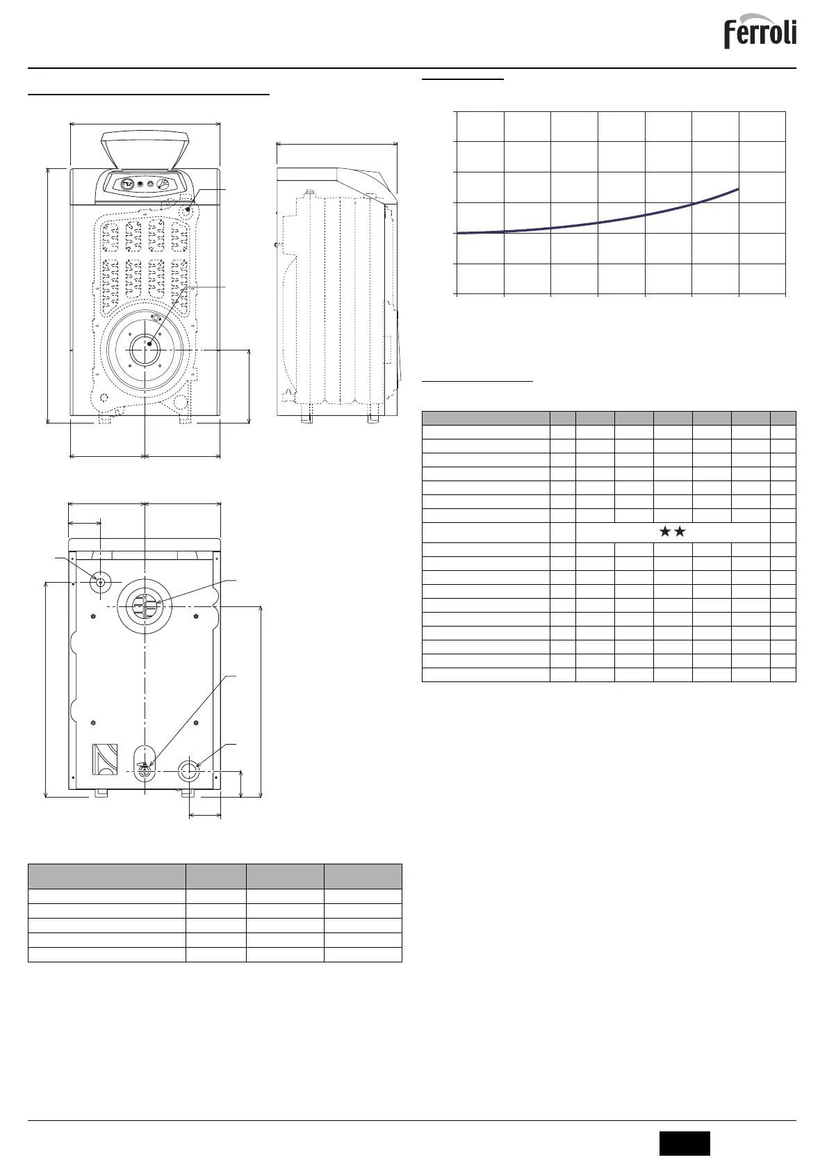
5.1 Dimensions, connections and main components
fig. 5 - Dimensions, connections and main components
a1 System delivery - 1” 1/2”
a2 System return - 1” 1/2”
a3 Heating system drain - 1/2”
a4 Flue connection
a5 Burner connection
34 Safety and heating temperature bulb
5.2 Pressure loss
Pressure loss water side
fig. 6 - Pressure loss
A mbar
B Flowrate l/h
5.3 Technical data table
Model
C
mm
a4
Ø mm
a5
Ø mm
ATLAS 32
400 120÷130 115
ATLAS 47
500 120÷130 115
ATLAS 62
600 120÷130 115
ATLAS 78
700 120÷130 115
ATLAS 95
800 120÷130 115
500
C
850
245
250 250
250 250
626
705
105
a1
a2
a3
a4
85
105
34
a5
Model ATLAS 32 ATLAS 47 ATLAS 62 ATLAS 78 ATLAS 95
Number of elements n° 3 4 5 6 7
Max. heating capacity kW 34.9 51.6 67.7 85.6 103.2 (Q)
Min. heating capacity kW 17.0 34.3 45.8 59.0 70.8 (Q)
Max. heat output in heating kW 32 47 62 78 95 (P)
Min. heat output in heating kW 16 32 43 55 66 (P)
Efficiency Pmax (80-60°C) % 91.7 91.1 91.5 91.1 92
Efficiency 30% % 94.3 93.5 94.0 93.5 93.8
Efficiency class Directive 92/42 EEC
Max. working pressure in heating bar 6 6 6 6 6 (PMS)
Min. working pressure in heating bar 0.8 0.8 0.8 0.8 0.8
Max. heating temperature °C 95 95 95 95 95 (tmax)
Heating water content l 18 23 28 33 38
Protection rating IP X0D X0D X0D X0D X0D
Power supply voltage V/Hz 230/50 230/50 230/50 230/50 230/50
Empty weight kg 127 166 205 244 283
Combustion chamber length mm 350 450 550 650 750
Combustion chamber diameter mm 300 300 300 300 300
Pressure loss fume side mbar 0.2 0.27 0.4 0.4 0.63
0
10
20
30
40
50
60
2000 2500 3000 3500 4000 4500 5000 5500
B
A
 Loading...