BLUEHELIX TECH RRT 24 H
204 EN
cod. 3541C662 - Rev. 00 - 09/2020
4.5 Diagrams
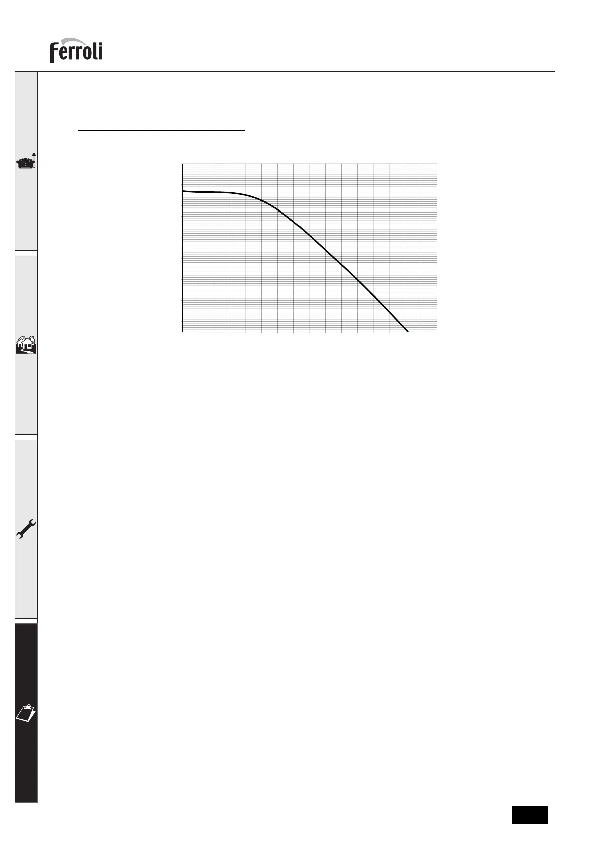
Residual head available for system
BLUEHELIX TECH RRT 24 H
fig. 57- Residual head available for system
4.6 Wiring diagram
16 Fan
32 Heating circulating pump
34 Heating temperature sensor
44 Gas valve
72 Room thermostat (not supplied)
81 Ionization/ignition electrode
95 Diverter valve
114 Water pressure switch
138 External sensor (optional)
139 Remote timer control (optional)
155 Hot water tank probe (optional)
186 Return sensor
191 Fume temperature sensor
A ON/OFF switch (configurable)
0.0
0.5
1.0
1.5
2.0
2.5
3.0
3.5
4.0
4.5
5.0
5.5
6.0
6.5
7.0
7.5
8.0
0 0.1 0.2 0.3 0.4 0.5 0.6 0.7 0.8 0.9 1 1.1 1.2 1.3 1.4 1.5 1.6
H(mCA)
Q (m3/h)
 Loading...