12
DOMIcompact F 24 D
It is essential to install the isolation valves supplied between the boiler and heating system, allowing the
boiler to be isolated from the system if necessary.
The safety valve outlet must be connected to a 15 mm pipe to allow safe discharge to the outside
ground in the event of over-pressure in the heating circuit. If this is not done, and the drain valve
opens and floods the room, the boiler manufacturer is not to be held responsible. The pipework
must have a continuous fall from the boiler, The outlet should face back against the outer bri-
ckwork or building face to prevent harm or injury from hot water discharging in the evet of an
over-pressuried system.
Make the boiler connection in such a way that its internal pipework is free of stress.
If a check valve is installed on the tap water circuit (where applicable), it is necessary to mount a safety
valve between the boiler and this circuit (check valve minimum 3 meters from boiler).
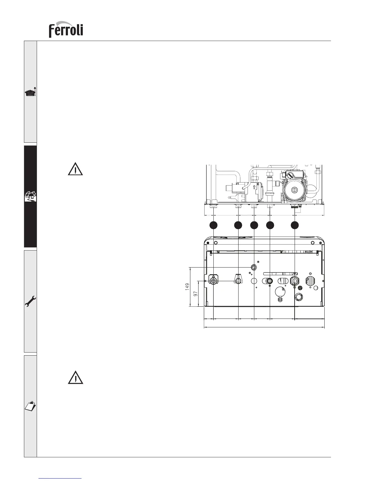
fig. 6
2.3 Boiler water connections
The heating capacity of the unit should be previously established by calculating the building’s heat
requirement according to current regulations. For efficient operation and long life of the boiler, the
plumbing system must be well designed and always complete with all those accessories that guarantee
regular operation and running, ie room thermostat, trv’s and automatic bypass etc .
If the flow and return pipes follow a path where air pockets could form in certain places, it is esential
to install air vent valves at these points. Also, install a type “A” drain cocks at the lowest point s in the
system to allow its complete draining. when required The temperature differential between the flow
manifold and the return to the boiler should not exceed 20° C.
A minimum flow of 6 litres/min is requied through the heat exchanger, it is therefore essential to fit an
automatic by-pass a min of 3 metres away from the appliance, This should be calibrated on site.
Do not use the water system pipes to
earth electrical appliances.
Before installation, carefully flush all the pipes
of the heating system to remove residues or
impurities that could affect the unit’s efficient
operation (BS 7593 Building regs Doc L).
Make the connections to the appliance as
shown in fig. 6.
1 2 3 4 5
35 95 60 60 95 113
36 95 114956060
460
Key
1 Heating system flow Ø 3/4”
2 Hot water outlet Ø 1/2”
3 Gas inlet 1/2”
4 Tap water inlet Ø 1/2”
5 Heating system return Ø 3/4”
 Loading...