Ferroli F24
33
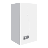
7.08 Removal of burner (fig. 36)
• Isolate gas and electricity supplies
• Remove outer case (two screws bottom rear
corners)
• Remove room sealed cover
• Disconnect ignition and flame rectification
leads "A"
• undo gas rail union "B"
• Undo two screws securing the burner assembly
to the boiler combustion chamber "D"
• Withdraw the burner assembly
7.09 Injectors (fig. 36)
• Proceed as 7.08
• Remove fixing screw "C" on both
sides of gas collector
• Remove gas collector
• Unscrew and remove injectors;
• Clear or change injectors
C
A
B
Fig. 36
D
D
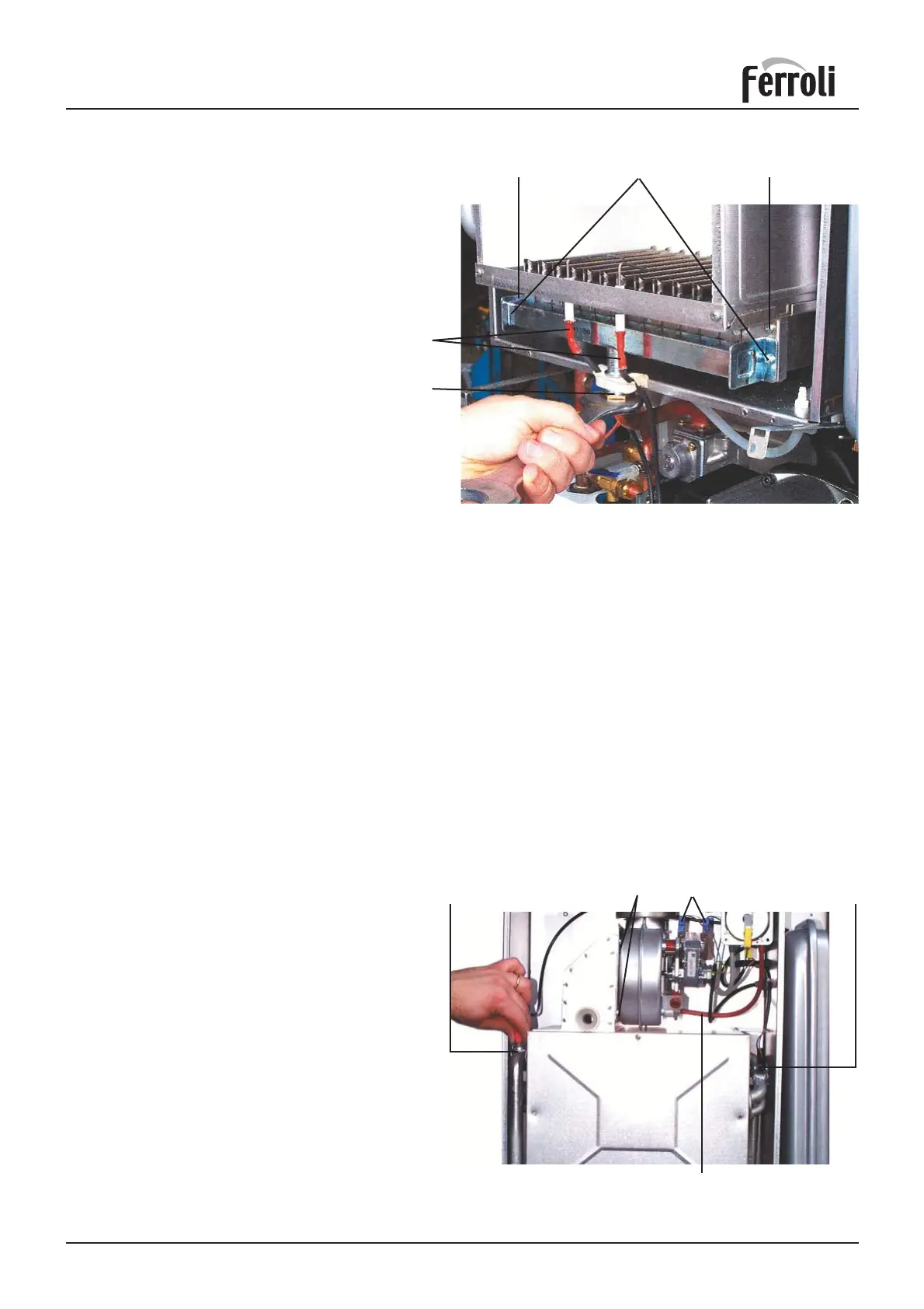
7.10 Removal of fan (fig. 37)
• Isolate gas and electricity supplies
• Remove outer case (two screws bottom rear
corners)
• Remove room sealed cover
• Disconnect fan electrical leads "A"and note
positions
• Disconnect air pressure tubes from air pressure
switch "B" + note positions
• Undo two screws securing fan assembly "C"
• Remove fan from boiler
• Swap mounting plate over to new fan + replace
in reverse order
7.11 Limit thermostat, or overheat cut off
thermostat (fig. 37)
• Isolate electricity
• Remove outer case (two screws bottom rear
corners)
• Remove room sealed cover
• Identify the location of thermostat from fig. 37
• Pull out thermostat from tube, with its spring
• Remove electrical connections from thermostat
• Remove spring from thermostat
• Replace in reverse order
Fig. 37
Overheat cut off Limit thermostat
C
A
B