Ferroli F24
34
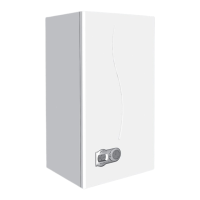
7.12 Spark or fl ame detect electrode (fig. 38)
• Isolate gas and electricity supply
• Remove outer case (two screws bottom rear
corners)
• Open room sealed compartment and
combustion chamber
• Identify electrode from fig. 38
• Unplug electrical connection "A" from sensing
electrode
• Remove fixing screw and remove flame detect
electrode
• Remove the two fixing screw from spark
electrode plate and remove it.
Spark
A
Flame
detect
Fig. 38
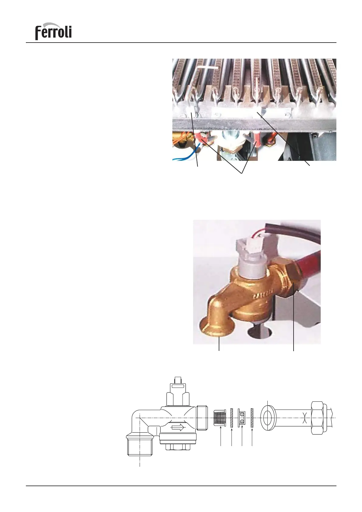
7.13 D.H.W. fl owmeter
• Isolate electricity and water supplies
• Open a hot water tap to release water pressure
from the domestic side of the heat exchanger,
close tap.
• Remove outer case (two screws bottom rear
corners).
• Remove two screws from control panel and tilt
forward
• Take off protective cover from main PCB and
unplug flow meter lead from terminal X4.
• Place a piece of cloth or some other absorbent
material over rear of control panel to catch
any drops of water that may be released when
removing the flow meter
• Using a 24mm open ended spanner, undo flow
meter unions "A" and "B" taking care not to
twist the copper tubing (access through base
panel).
• Remove flow meter, check + clean filter +
restrictor + fit to new flow meter.
• Reassemble in reverse order.
AB
Fig. 39a
37 3938 38
Key
37 Cold water inlet filter
38 Gasket
39 Cold water flow limiter
Take care on correct position of
components as reported in fi g. 39b
Fig. 39b