15
DOMINA OASI F 24 - 30 E
FERELLA BOIL F 24 - 30 MEL
KEA AIR COMPACT E
Version - 09.2002
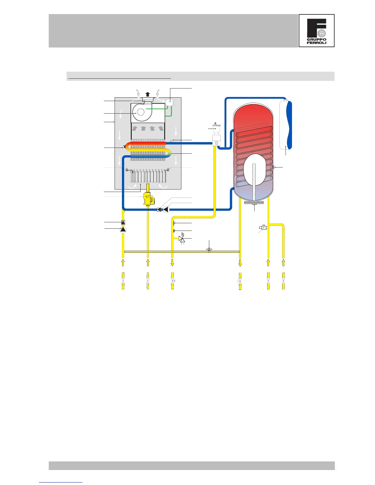
2.2 Hydraulic circuit – tap water
Hydraulic diagram for tap water
20
82
5
29-187
16
-
+
44
7
81
43
32
14
114
34
11 10
49
50
222
36
97
155
130
179
179
74
8
9 192
151
56
The tap water is supplied via an integrated boiler. It is heated indirectly by a coil in the boiler. The primary water
circulates in the coil thanks to a pump and is kept at a temperature of 85°C by the heating sensor. When the
temperature detected by the boiler sensor is 1°C lower than the set temperature, the heating pump stops and
the tap-water pump starts up immediately. In this way, heating is turned off and the boiler exchanges with the
closed circuit water that in its turn yields the heat to the tap water contained in the boiler.
Key
5 Airtight chamber
7 Gas inlet
8 Tap water outlet
9 Tap water inlet
10 System delivery
11 System return
14 Safety valve
16 Fan
20 Burner assembly
29 Fume outlet manifold
32 Heating circulator
34 Heating temperature sensor
36 Automatic air vent
43 Air pressure switch
44 Gas valve
49 Safety thermostat
50 Heating thermostat
56 Expansion tank
74 Heating system cock
81 Ignition electrode
82 Detection electrode
97 Magnesium anode
114 Water pressure switch
130 Boiler circulator
151 Boiler drain cock
155 Boiler temperature sensor
179 Check valve
187 Fume diaphragm
192 Recirculation
222 Copper exchanger
 Loading...