27
DOMINA OASI F 24 - 30 E
FERELLA BOIL F 24 - 30 MEL
KEA AIR COMPACT E
Version - 09.2002
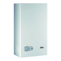
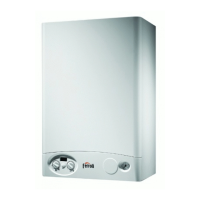
2.6 Electrical circuit
Electrical terminal board
Follow the instructions given in the figure to access the electrical connection terminal board.
The layout of the terminals for the various connections is given in the wiring diagram.
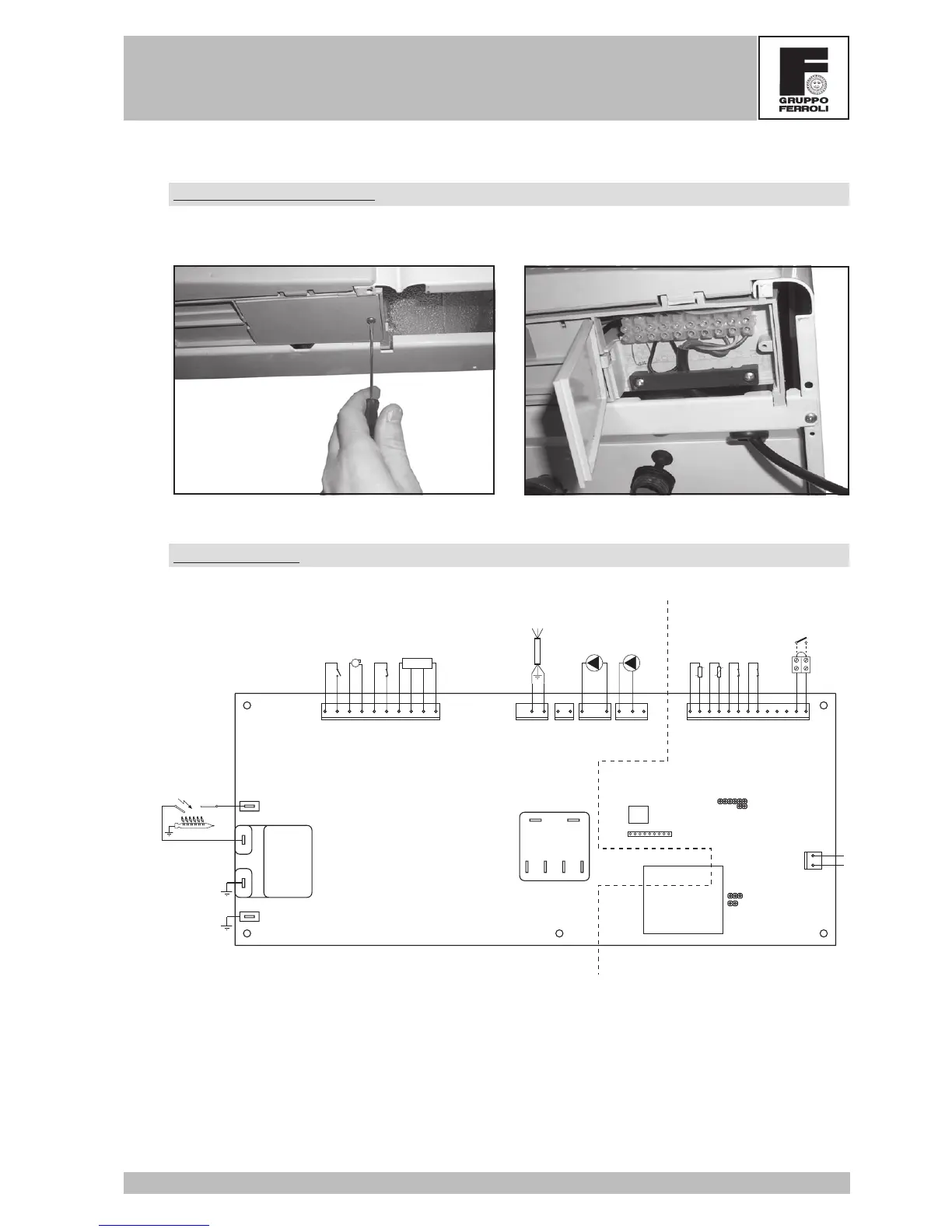
Wiring diagram
X6
X1
X2 X3
X4
12121312345678910 12345678910111213
21
X5
TEST
Transformer
X12
12
123456789
X10
X8
X7
81 82
PMF03F
JP02
JP01
Nat/LPG
X11
230V 24V
230V
24V
X9
13 2
MV1
MV2
MV3
MV4
98
72
5011415534
32
230V
50Hz
130
44491643
Key
16 Fan
32 Heating circulator
34 Heating temperature sensor
43 Air pressure switch
44 Gas valve
49 Safety thermostat
50 Heating thermostat
72 Room thermostat (not supplied)
81 Ignition electrode
82 Detection electrode
114 Water pressure switch
130 Tap water circulator
155 Boiler sensor
N.B. Respect the phase and neutral connections
 Loading...