601
26
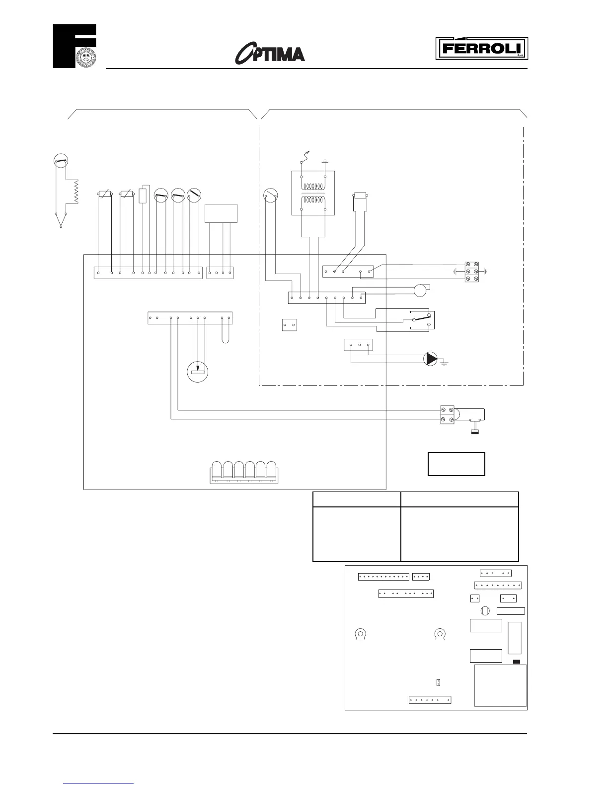
68 Control box with P.C.B.
72 Room thermostat (not fitted)
80 24V roomstat terminal blocks
114Low water pressure switch
136Flowmeter
145C.H. pressure gauges
P1 = C.H. max. output
P2 = D.H.W. temperature (factory set)
JP1 - JP4 Jumper links on P.C.B.
JP1 Is not required
JP4 Must be fitted
16 Fan
23 Thermocouple
24 spark electrode
31 Air pressure control damper
32 Central heating pump
34 C.H. flow temperature sensor
42 D.H.W. temperatuure sensor
43 Air pressure switch
46 Operator gas valve
47 Modulating regulator
(Modureg) gas valve
49 Overheat cut-off thermostat
50 Heat exchan. limit thermostat
51 Heat exchan. frost thermostat
60 Extended control knob gas valve
63 C.H. boiler thermostat
66 Microswitch combination
gas valve
67 Ignition transformer
12 1
TR1
X4
X6
234
X2
RY1
X1
2AT
230V
50Hz
1
11 10
7263512 910
12
P1
X3
6 5
3
4
1
F1
987654321
X8
123456789
X5
1
2
X7
JP4
13
L7
RY2
RY4
JP1
P2
NOTE:
THE TRANSFORMER ON THE P.C.B.
HAS A BUILT-IN OVERHEAT
PROTECTION.
IF THIS IS OPEN, ALL LED'S WILL
BE OFF BUT THE C.H. PUMP (32)
WILL RUN SWITCH OFF THE BOILER
FOR AT LEAST 20 MINUTES
SHORT CIRCUIT 12-13
- BOILER STARTS FOR C.H.
- WAITING TIME IS EXCLUDED
- MAX BURNER PRESSURE C.H.
CAN BE CHEDKED/SET WITH P1
CONNECTOR X3
A D.H.W. FLOW-
SWITCH (ON-OFF) CAN
BE CONNECTED TO
TERMINALS 1 AND 3
CONNECTOR X2
L
2
1
N
24
5
23
4
24V
80
5
72
49
43
16
51
34825
-
62791
X6
X3
X7
X4
X2
11
6
12
10 5 3
1
62713
4
12
5
213
21
1
X8
678
47
34
34
50
136
63
9
OUT
10
X1
230V ~ 50 Hz.
11
24 V
230V
N
L
80
3124
X5
VMF7
42
+
812
32
66
67
46
LD1
114
CONNECTOR X7
1-2 = 230 V