T-ONE C HE
13EN
cod. 3541D730 - Rev. 00 - 05/2013
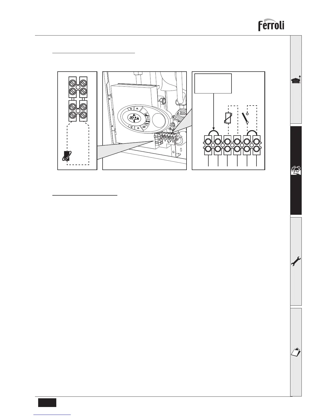
Accessing electrical terminal block
The electrical connections terminal block can be accessed after removing the casing. The layout of the terminals for the
various connections is given in the wiring diagram in fig. 39.
fig. 18 - Electrical terminal block
Room thermostat (optional)
B
CAUTION: THE ROOM THERMOSTAT MUST HAVE VOLTAGE FREE SWITCH CONTACTS.
CONNECTING 240V TO THE SWITCH TERMINALS OF THE BOILER WILL IRREPARABLY DAMAGE THE
BOILER PCB.
When connecting either a room thermostat or remote timer control, remove the jumper on the terminal block
and connect the volt free switch connections across these terminals. If a remote timer control and room ther-
mostat are required then these must be connected in series.
 Loading...