Modular valve terminal with integrated controller CPX-CEC-...
21
1.5 CPX-CEC-... PLC configuration
The PLC configuration includes a description of the target system settings. The description specifies which
controller components are used and how they are configured.
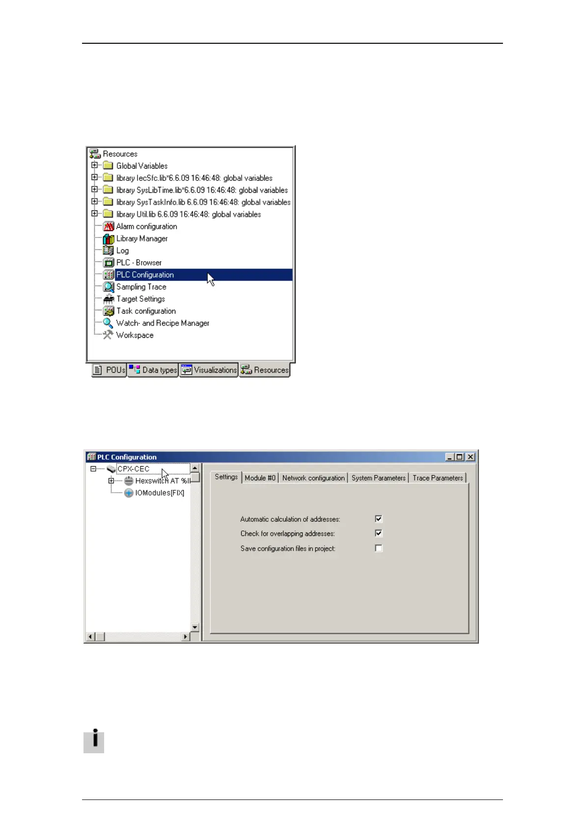
• Select the "Resources" tab in the Organizer object.
Figure: Opening the PLC configuration
• Double-click on the "PLC Configuration" item to open the respective window.
The target system and all components (inputs, outputs, CANopen bus, etc.) are displayed in a tree
structure in the left section of the "PLC Configuration" dialog window.
Figure: PLC configuration
Other settings are available on different tabs. The most important settings are described in the following
chapters.
Appropriate variables must be defined so that outputs and inputs or diagnostic information and parameters
can be read and written. These variables are usually created as global variables and are defined in the
declaration part using the following syntax:
o Variable name AT address: data type;
Refer to the CoDeSys general online Help for more detailed information on defining global
variables.

 Loading...