1
Assembly instructions (original: de)
8031389
1401NH
[8031391]
†‡
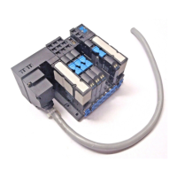
Terminal CPX / Valve terminal VTSA
CPX, CPX-M, VTSA, VTSA-F
Festo SE & Co. KG
Postfach
73726 Esslingen
Germany
+49 711 347-0
www.festo.com
1. Safety instructions and notes on mounting .............................................. 1
2. Parts list ................................................................................................... 2
3. Explanations of terms ..............................................................................
2
4. Intended use ............................................................................................ 2
5. Wall mounting .......................................................................................... 3
5a. Check positions of the moun
tings ....................................................... 3
5b. Assemble mountings ...........................................................................
3
5c. Overview of the mounting poi
nts ......................................................... 4
5d. Mount VTSA/VTSA-F-modules (65 mm) ............................................... 5
6. Mounting system assembly ..................................................................... 6
6a. C
heck positions of the moun
tings ....................................................... 6
6b. Assemble mountings ........................................................................... 6
6c. Mount CPX-terminal to the mo
unting system ....................................... 6
7. H-rail mounting ........................................................................................ 7
7a. Mount H-
rail ........................................................................................ 7
7b. Mount CPX-terminal to H-rail ............................................................... 7
1)
2)
1)
SL1 = Severity level 1
SL2 = Severity level 2
2)
CPX terminals 1 with 1 … 3 VTSA/VTSA-F-modules a maximum of one vertical stacking
component per VTSA/VTSA-F-module.
CPX terminals 1 with 4 … 5 VTSA/VTSA-F-modules a maximum of one vertical stacking
component on the VTSA/VTSA-F-valve terminal.
CPX terminals 1 with more than 5 VTSA/VTSA-F-modules and at least one vertical stacking
on the VTSA/VTSA-F-valve terminal no mounting system assembly permitted.
1. Safety instructions and notes on mounting
Warning
Electric voltage.
Injury (death) due to electric shock.
Switch off power supply before assembly work.
Caution
Unexpected movement of components.
Injury due to electric shock, impact, squeezing.
Switch off compressed air before assembly work.
Note
Electrostatic charge.
Damage to the internal electronics.
Electrostatically discharge assembly personnel prior to assembly work.
Note
Malfunction due to incorrect earthing.
Earth in accordance with regulations
CPX-system description: Potential equalisation.
Note
Malfunction and material damage due to incorrect assembly.
Plan sufficient space:
– permit heat dissipation through air circulation
CPX-system description
VTSA/VTSA-F-description of pneumatics.
– permit access to the connections.
Requirements of the mounting surface:
– torsion-free operation of the product
– acceptance of the weight and other forces that occur.
Observe assembly conditions ( following tables).
Assembly Wall Mounting
system
H-rail
CPX-modules (plastic) √ − √
CPX-modules (metal) and
VTSA/VTSA-F-modules
(18 … 52 mm)
√ √ √
VTSA/VTSA-F-modules (65 mm) √ − −
Resistance to vibra-
tion/ resistance to
shock
in accor-
dance with
EN 60068
Wall Mounting
system
H-rail
Vibration Part 2-6 SL2
1)
SL1 SL2
2)
−
Shock Part 2-27 SL2 SL1 SL2
2)
−
Continuous shock Part 2-27 SL1 SL1 SL2
2)
−
Vibration load
Frequency range [Hz] Acceleration [m/s
2
] Displacement [mm]
SL1 SL2 SL1 SL2 SL1 SL2
2 … 8 2 … 8 − − ±3.5 ±7
8 … 27 8 … 27 10 10 − −
27 … 58 27 … 60 − − ±0.15 ±0.7
58 … 160 60 … 160 20 50 − −
160 … 200 160 … 200 10 10 − −
Shock load
Acceleration [m/s
2
] Duration [ms] Shocks per direction
SL1 SL2 SL1 SL2 SL1 SL2
±150 ±300 11 11 5 5
Continuous shock load
Acceleration [m/s
2
] Duration [ms] Shocks per direction
±150 6 1000