Do you have a question about the Festo CPX-FB33 and is the answer not in the manual?
Defines the intended application and purpose of the bus nodes.
Explains danger categories and pictograms used in the manual.
Provides essential safety and general guidance for installation.
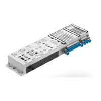
Details the connection interfaces and display LEDs on the bus node.
Explains the procedure for physically attaching and detaching the bus node.
Covers configuring the bus node using DIL switches and memory cards.
Describes how to access the DIL switches and memory card.
Details how to set the DIL switches for various operating modes and functions.
Explains the role of the memory card for configuration data and device replacement.
Covers the procedure for replacing a bus node, including using a memory card.
Details how to connect the bus node to the PROFINET network.
Provides general guidelines and requirements for connecting to PROFINET networks.
Summarizes the available connections, connectors, and cable types for the bus node.
Describes the network connection interface for the CPX-FB33 model.
Describes the network connection interface for the CPX-M-FB34 model.
Describes the network connection interface for the CPX-M-FB35 model.
Explains how to maintain the specified IP rating for connections.
Details the power supply requirements and safety precautions.
Provides general guidance and safety notes for commissioning.
Details the rules and methods for addressing modules and the bus node.
Details the rules and methods for addressing modules and the bus node.
Outlines fundamental rules for assigning addresses to modules and devices.
Guides users on commissioning using Siemens SIMATIC STEP 7 software.
Covers essential preparations, including importing device master files.
Explains how to obtain and prepare the necessary device master files.
Details how to select the appropriate GSDML file based on system compatibility.
Guides on creating and setting up a new automation project in SIMATIC Manager.
Explains how to configure the PLC/Master system within the hardware configuration.
Describes the process of installing the GSDML file into the hardware catalogue.
Covers the fundamental steps for configuring the hardware in the software.
Explains how to find and identify the CPX terminal on the network.
Guides on selecting the correct CPX terminal station symbol in the hardware configuration.
Details how to assign a unique device name to the CPX terminal.
Explains how to configure the "Fast Start-up" (FSU) function for quicker terminal startup.
Covers the manual assignment or automatic allocation of IP addresses.
Explains how to use MAC addresses for device identification and addressing.
Describes how to determine the addresses for network ports TP1 and TP2.
Covers the process of configuring the CPX terminal within the PROFINET system.
Guides on adding bus nodes and modules into the configuration table.
Explains how to change the I/O start addresses for modules.
Details how to modify the diagnostics address for the CPX terminal.
Covers how to set individual reactions and parameters for the CPX terminal.
Explains how parameters are applied during system startup.
Guides on parameterizing the CPX terminal using Siemens STEP 7 software.
Details parameterization using the CPX-MMI operator unit.
Explains parameterization using the Festo Maintenance Tool (CPX-FMT).
Lists and describes various bus node parameters for configuration.
Provides a practical example of parameterization for signal processing.
Covers the Identification and Maintenance (I&M) function for device information.
Details how to configure the bus node for the Remote Controller operating mode.
Provides a checklist for verifying successful commissioning.
Summarizes the available diagnostic functions and their benefits.
Explains the meaning of the LEDs on the bus node for status indication.
Details the meaning of network and connection status LEDs (NF, M/P, TP1, TP2).
Explains the meaning of CPX terminal status LEDs (PS, PL, SF, M).
Describes how status bits provide diagnostic messages.
Covers the use of the I/O diagnostic interface for detailed diagnostics.
Explains how PROFINET facilitates comprehensive diagnostics.
Guides on performing online diagnostics using Siemens STEP 7 software.
Lists general characteristics and power supply data for the CPX-FB33 bus node.
Lists general characteristics and power supply data for the CPX-M-FB34 bus node.
Lists general characteristics and power supply data for the CPX-M-FB35 bus node.
Provides network-specific characteristics and protocol information for all bus nodes.
Explains the different operating modes for the bus node.
Describes the Remote I/O operating mode, its functions, and communication.
Details the Remote Controller operating mode, requirements, and functions.
An alphabetical index of topics covered in the manual for quick reference.
| Model | CPX-FB33 |
|---|---|
| Operating voltage | 24 V DC |
| Display Resolution | 320 x 240 pixels |
| Fieldbus type | PROFIBUS DP |
| Number of digital inputs | 0 |
| Number of digital outputs | 0 |
| Protection class | IP65 |
| Display Type | TFT |
| Touch Technology | Resistive |
| Protection Rating | IP65 front |
| Communication Protocols | PROFIBUS DP |