1. Installation
1-4
Festo P.BE-CPX-PNIO-E N en 1407c English
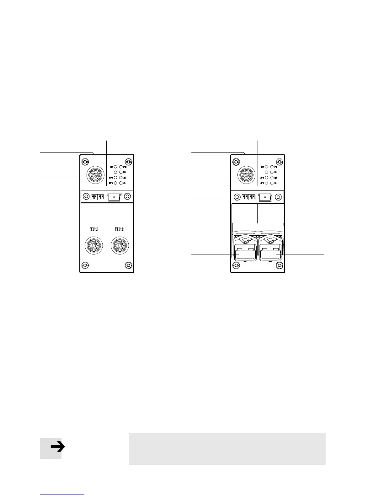
1.2 Electrical connection and display components
You will find the following connection and displ ay co mpon-
ents on the bus node for PROFI N ET:
1
2
3
4
CPX-FB33 CPX-M-FB34
CPX-M-FB35
2
2
3
4
2
55 1
1
PROFI N ET-specific network/bus status
LEDs and CPX-specific LEDs
2
Mains connection
CPX-FB33: 2xM12socket,
D-coded, 4-pin
CPX-M-FB 34 : 2 x RJ45 socket,
Push-pull,
AIDA-conforming
CPX-M-FB35: 2 x SCRJ-Buchse,
Push-pull,
AIDA-conforming
3
Cover for DIL switch and memory card
4
Service interface
for operator unit (CPX-MMI; V24 inter-
face) und USB adapter (for CPX-FMT)
5
Label with MAC-ID and CPX revision
code (“Rev ...”)
Fig. 1/1: Connection and display components on the bus node for PROFINET
Note
Use cover caps to seal unused connections ( Section 1.7).