Do you have a question about the Festo CPX and is the answer not in the manual?
Overview of the electronic components of the CPX terminal system.
Covers the installation and commissioning process for CPX terminals.
Specifies the intended applications and operational environment for CPX terminals.
Outlines danger categories and safety guidelines for proper equipment usage.
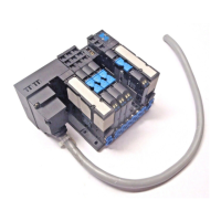
Describes the general structure and design variants of CPX terminals.
Details various electric and pneumatic modules used in CPX terminals.
Explains the power supply concept and interlinking blocks for CPX terminals.
Provides general guidelines for assembling and dismantling CPX terminal modules.
Details the process of assembling electric modules with interlinking blocks.
Explains methods for fitting CPX terminals onto H-rails and walls.
Covers general instructions for installing CPX terminals, including cable connections.
Explains configuration for CPX bus nodes and pneumatics for proper installation.
Guides on selecting appropriate power supply units and understanding voltage forwarding.
Outlines the step-by-step procedure for commissioning CPX terminals.
Explains different parameter types and their configuration for CPX terminals.
Details CPX terminal start-up behavior and system start parameter settings.
Introduces the diagnostic possibilities and options for the CPX terminal.
Explains the use of LEDs on CPX bus nodes and I/O modules for diagnosis.
Describes diagnosis using status bits and the I/O diagnostic interface for fault finding.
Lists error numbers, their classes, and common fault messages for troubleshooting.
Provides general technical specifications including environmental and compatibility data.
Guides on calculating maximum cable length considering voltage drop and cable parameters.
Explains methods to access internal parameters and data based on fieldbus protocol.
Details system parameters like Monitoring, Fail Safe, Force Mode, and System Start.
Describes module-specific and channel-specific functions and parameters.
Explains configuration of diagnostic memory and the structure of logged fault data.
Provides information on system status, module numbers, and error numbers for diagnosis.
Details module identification data like code, revision, and serial number.
Explains how input debounce time suppresses spurious signals and ensures reliable input recognition.
Details how signal extension times help recognise short signals reliably by the controller.
Describes functions like Forcing, Fail Safe, and Idle Mode for influencing signal states.
Explains the operation of diagnostic memory filters for controlling fault registration.
Covers activation and deactivation of monitoring functions for system and module parameters.
| Interfaces | Ethernet, USB, RS232 |
|---|---|
| Operating voltage | 24 V DC |
| Operating system | Windows CE |
| Protection class | IP65 |
| Operating temperature | 0 - 50 °C (depending on the model) |