5. Diagnostics and error handling
5−12
Festo P.BE−CPX−SYS−EN en 0902e
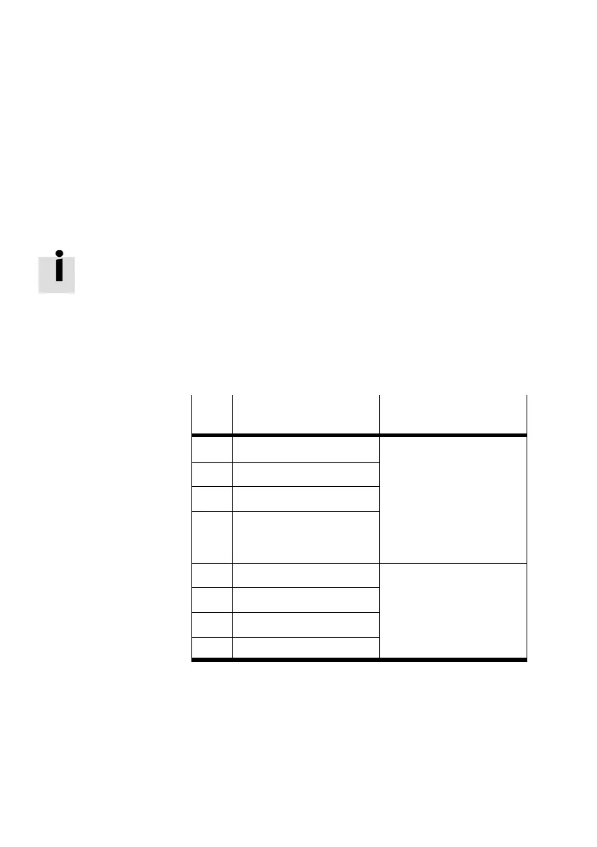
5.2.1 Structure of the status bits
Irrespective of the CPX bus node used, the CPX terminal pro
vides 8status bits for displaying common diagnostic mess
ages (global error messages).
Status bits are configured like inputs. The input addresses,
which are to be assigned to status bits, depend on the field
bus protocol used (see manual for the specific CPX
bus
node).
The status bits supply coded diagnostic information. Bits 0 to
3 specify the module types in which faults have occurred. Bits
4 to 7 specify the type of fault.
Bit
Diagnostic information
with 1−signal
Description
0 Error at valve Module type in which an
1 Error at output
error has occurred
2 Error at input
3 Error in analogue module/
function module or techno
logy module
4 Undervoltage Type of error
5 Short circuit/overload
6 Wire break
7 Other error
Tab.5/3: Structure of the status bits
If all status bits supply a 0−signal, no fault will be registered.