1. Installation
1-25
Festo P.BE-CPX-PNIO-EN en 1407c English
1.6.4 Network interface of the CPX-M-F B34
There are two RJ45 push-pull sockets (AIDA-compliant) on the
CPX-M-FB34 for the network connection:
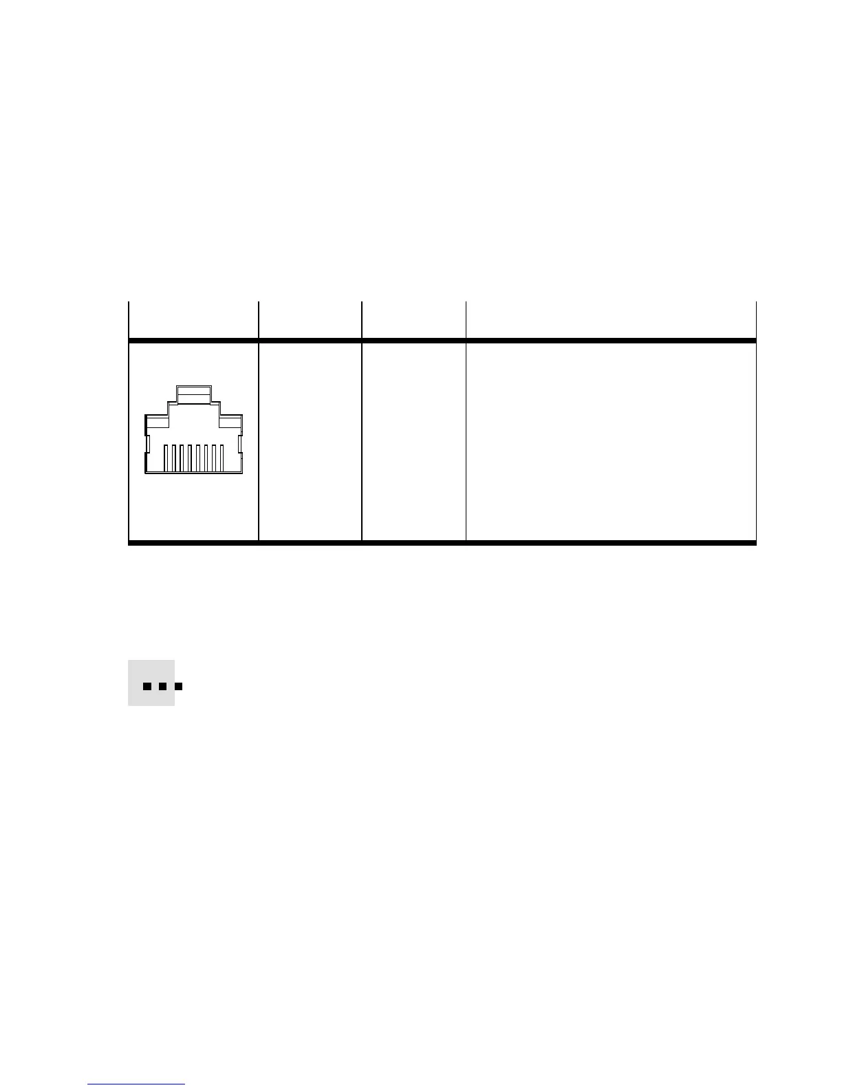
Socket
Pin Signal Explanation
RJ45, push-pull
1
2
3
4
5
6
7
8
1
2
3
4
5
6
7
8
Housing
TD+
TD–
RD+
n.c.
n.c.
RD–
n.c.
n.c.
Shield/FE
Transmission data (transmit data, TD) +
Transmitted data –
Receivedata(receivedata,RD)+
Not connected
Not connected
Received data –
Not connected
Not connected
Shield/functional earth (FE)
Tab. 1/8: Pin allo cation of the network interfaces of the CPX-M-FB34 (RJ45)
Connection with plug from Festo
Connect the CPX terminal to the network with a F esto plug
FBS-RJ45-PP-GS. The plug is designed for Ethernet cable with
cable diameter of 5 ... ... 8 mm.
To achieve the required degree of protection, e.g. IP65/IP67:
– Use Festo plugs.
– Seal unused co nn ections (see section 1.7).