2. Commissioning
2-43
Festo P.BE-CPX-PNIO-EN en 1407c English
2.7 CPX-terminal configuration
2.7.1 Allocate configuration table (insert bus nodes and modules)
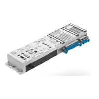
In the subsequent steps, you take the bus node and individu-
al mo dules of your CPX terminal ( 1 in Fig. 2/11) from the
hardware catalogue into the configuration table ( 2 ).
The CPX modules are subdivided within the hardware cata-
logue into field-device groups ( 4 in Fig. 2/11): analogue
modules, digi tal modules, pneumatic interfaces, pneumatic
modules and technology modules. The bus nodes CPX-FB33,
CPX-M-FB34 and CPX-M-FB35 form their own group in this
environment (“Bus nodes”).
Thefield-devicegroupsor“Busnodeandmodulefolder”are
located under the station symbols ( 3 ).
1. S tart the PROFINET hardware configuration in your config-
uratio n and programming software (e.g. HW Config in
Siemens STEP 7).
2. If the Hardware Catalogue has not been opened:
Click on the catalogue symbol or use the keyboard com-
bination [Ctrl] + [K].
The hardware catalo gue is displayed.
3. In the Hardware Catalogue, open the folder:
– “\PROFINET-IO\Additional Field Devices\Valves\Festo
CPX-Terminal ” (Engli sh language versi o n of the soft-
ware)
or
– \PROFINET-IO\Wei tere Feldgeräte\Ventile\Festo CPX-
Terminal.