5.4 Enter the security code (EDIT mode)
Requirement: The sensor is ready for operation (RUN mode).
1. Press the Edit button.
è The EDIT mode is active. If the security code is activated, the parameter
entry option is blocked: [Lock] flashes.
2. Enter security code set with A or B key.
3. Press the Edit button briefly.
è [OutA] flashes. The parameter entry option is unblocked.
5.5 Configuring switching output (EDIT mode)
Note
The process is the same for configuring the switching outputs for OutA and
OutB. In the following, the process is described using the switching output OutA.
Menu structure è Fig. 20.
Requirement: The sensor is ready for operation (RUN mode).
Set threshold value comparator _I¯, window comparator _I¯I_, auto difference
monitoring d_I¯I_
1. Press the Edit button briefly.
è [Edit] appears. [OutA] flashes.
2. Press the Edit button briefly.
è [Fctn] flashes.
3. With A or B key, select _I¯ or _I¯I_ or d_I¯I_.
4. Press the Edit button briefly.
è The set value is saved.
è The next adjustable parameter is shown.
5. Set parameters with A- or B-key.
6. Repeat points 4 and 5 until all parameters are set.
7. Press the Edit button.
è Switch to the RUN mode.
– Switching functions è Chapter 3.2
5.6 Change device settings (EDIT mode)
Requirement: The sensor is ready for operation (RUN mode).
1. Press the Edit button briefly.
è [Edit] appears. [OutA] flashes.
2. With A or B key, select special menu [Spec].
è [Spec] flashes.
3. Press the Edit button briefly.
è [Filt] flashes.
4. Set parameters with A- or B-key.
5. Press the Edit button briefly.
è The set value is saved
è The next adjustable parameter is displayed.
6. Repeat points 4 and 5 until all parameters are set.
5.7 Set analogue output (EDIT mode)
Requirement: The sensor is ready for operation (RUN mode).
1. Press the Edit button briefly.
è [Edit] appears. [OutA] flashes.
2. Select [InA] with the A-key or B-key.
è [Edit] appears. [InA] flashes.
3. Press the Edit button briefly.
è [Out] flashes.
4. Set parameters with A- or B-key.
5. Press the Edit button briefly.
è The set value is saved.
è The next adjustable parameter is shown.
6. Repeat points 4 and 5 until all parameters are set.
7. Press the Edit button.
è Switch to the RUN mode.
5.8 Replicating parameters (EDIT mode)
Requirement:
– The pre-configured sensor (master sensor) is ready for operation (RUN mode).
– Master sensor and device sensor have the same design regarding the paramet
ers (same device ID).
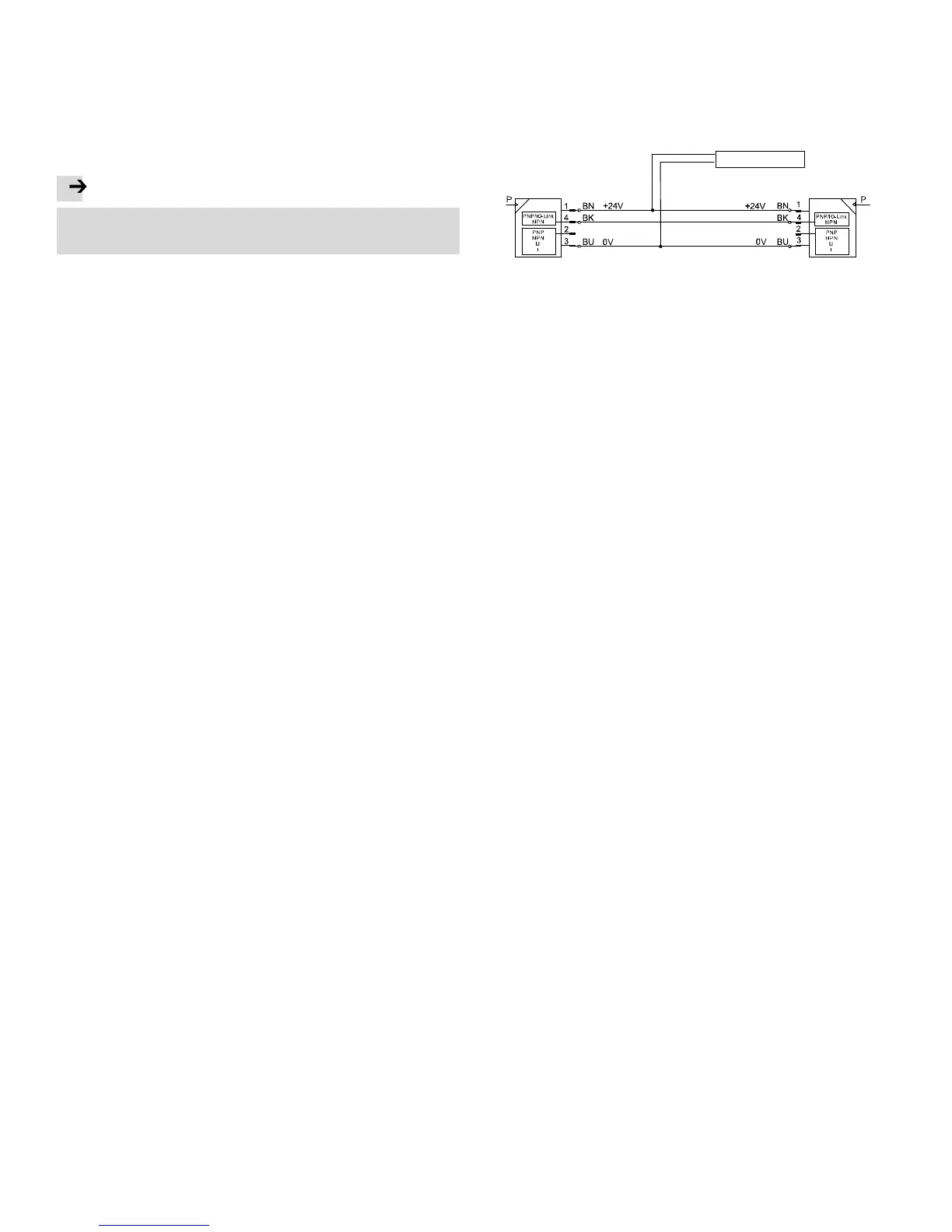
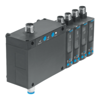
– The master sensor is connected with the device sensor (è Fig. 19).
– Parameterisation of the device sensor must not be blocked via IO-Link
®
.
– The device sensor is in an unswitched status (switching output PNP, display
OutA off).
Power supply
Master sensor
Device sensor
Fig. 19
1. Select special menu [Spec] at the master sensor via device settings.
2. Press the Edit button briefly until [MASt] appears.
3. With A or B key, select [ON].
4. Press the Edit button
è [REPL] / [RedY] appears.
5. Press A- or B-key.
è [REPL] / [RUN] appears briefly.
è The parameters are transmitted to the device sensor.
è [REPL] / [RedY] appears.
If an error occurs, an error message appears (è Fig. 21).
6. Repeat point 5 if an additional sensor should be parameterised.
7. Press the Edit button briefly.
è Switch to the RUN mode.