Translation of the original instructions
1 Further applicable documents
User documentation
Name, type Table of contents
Sensorbox, SRBC-CA3-N-20N-ZC-EX6 Operating conditions EX
Tab. 1
All available documents for the product èwww.festo.com/pk.
2 Safety
2.1 Safety instructions
The cable connector supplied is only for cable throughfeed.
– To ensure the specified degree of protection IP67, seal each cable entry tight
(cable connector, blanking plug).
2.2 Intended use
The sensorbox is intended for recording, electrical feedback and optical display of
the end positions of drives. Appropriate for operation are semi-rotary drives and
other products with a mechanical interface in accordance with VDI/VDE Directive
3845.
3 Service
If you have technical questions, contact the regional Festo contact
è www.festo.com.
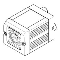
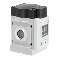
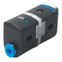
4 Product overview
Feature Value Description
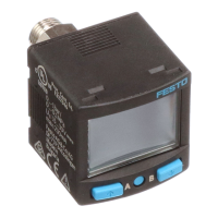
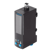
Type SRBC Sensorbox for process automation
Design C Sensorbox
Mechanical interface A3 Mounting adapter, hole pattern 30x80mm, height
20mm
Display type YR Position indicator yellow/red
Measuring range 90 0…90°
N Proximity sensors, inductive
R Reed with contact
Measuring principle
MW Potential-free contact, changer
2A 110 V AC
22A 250 V AC
20N 8.2VDC (NAMUR)
Nominal operating voltage
1 24 V DC
N NPN
P PNP
ZC 2-wire N/C contact (NC)
ZU 2-wire N/O contact (NO)
Switching element function
1W 1-pin toggle switch
Electrical connection C2 Screw terminal
Cable joint P20 M20x1.5, polymer
EU certification EX6 II 1GD
Tab. 2
1
Position indicator
2
Housing cover
3
Housing screws
4
Proximity sensor
5
Terminal strip
6
Shaft
7
Cable entry with cable connector or blanking plug
8
Mounting adapter with retaining screws
9
Earth connection (PE) on the inside of the housing wall
10
Shaft with cam and spring
Fig. 1
Presetting on delivery:
– Position indicator “closed”
– Switching point for “open” 90° anti-clockwise
5 Function
The shaft transmits the rotation of the drive to the visual position indicator.
Depending on the design, the cams actuate mechanical, inductive or magnetic
proximity sensors to provide the signals at the electrical output, terminal diagram
è Tab. 3 Terminal diagram of sensorbox SRBC.
6 Assembly and installation
For sensorboxes with type SRBC-...-2A and SRBC-...-22A:
WARNING!
Electric voltage
Injury due to electric shock.
• Switch off the power supply before opening the device.
6.1 Assembly
During assembly, observe the position indicator and ensure compliance with the
process fitting.
1. Place the sensorbox with mounting adapter in position and align it.
– Avoid axial load of the drive shaft.
2. Attach the mounting adapter.
– Retaining screws 8, tightening torque 6Nm ±10%
Mounting adapter
When replacing the sensorbox, observe tightening torque. Tightening torque
between mounting adapter and sensorbox: 10Nm ±10%
8121896
SRBC-...
Sensorbox
8121896
2019-10d
[8121898]
Instructions | Operating
Festo SE & Co. KG
Ruiter Straße 82
73734 Esslingen
Germany
+49 711 347-0
www.festo.com