6.5 Configuring the VPPM-...C1
Editing the pressure range and the a rrangement of the setpoint value display
1. In order to activate the EDI T mode, press th e EDIT button.
Only with active security locking - [Lock] flashes:
2. Press the UP/DOWN button until the desired security code is set and confirm
by pressing the EDIT button.
[Out] flashes.
3. Press the UP/DOWN button until [In] flashes in the display, then press the
EDIT button.
[min] flashes.
Editing the pressure regulation range:
4. Set the minimum pressure value with the UP/DOWN buttons, then press the
EDIT button.
[max] flashes.
5. Set the maximum pressure value with the UP/DOWN buttons, then press the
EDIT button.
The current setpoint value display type flashes.
– Either [mA] or [V ] flashes, depending on the variant of the VPPM-...C1
– or percent [%] flashes
– or [kPa], [psi] or [bar] flash, depending on the unit set in the SPEC menu.
Configuring the setpoint value display
6. Set the de sired display type using the UP/DOWN but tons, then press the ED IT
button.
The VPPM-...C1 is then in the RUN mode again.
Fig. 19
Configuring the switching output (Out)
Warning
Depending on the functions of the machine/system, the manipulation of signal
states can cause serious injury to human beings and damage to pro perty.
• Note that if the switching behaviour of the switching outputs is modified in
the EDIT mode, the new status will be effective immediately.
• Define the desired switc hing characteristics of switching output D3.
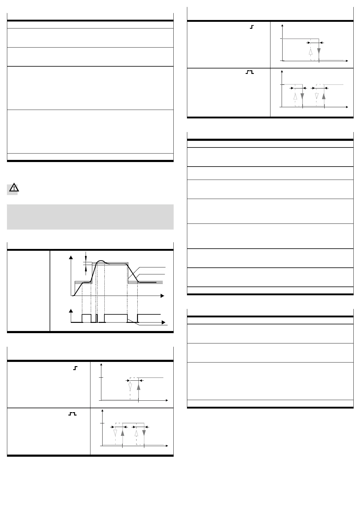
Switching points (SP...) and hysteresis (Hy)
With setting SP.O.
SP.O. signal
U[V]
p[bar]
t
t
Hysteresis
Actual value
Setpoint value
Fig. 20
Switching points (SP...) and hysteresis (Hy) with NO setting (normally open
contact)
With threshold
value comparator setting
P
1
0
Hy
OUT
SP
With window
comparator setting
Hy Hy
P
1
0
OUT
SP
min.
SP
max.
Fig. 21
Switching points (SP...) and hysteresis (Hy) with NC setting (normally closed
contact)
With threshold
value comparator setting
P
1
0
SP
Hy
OUT
With window
comparator setting
P
1
0
OUT
SP
min.
SP
max.
Hy
Hy
Fig. 22
Configuring the switching output
1. In order to activate the EDI T mode, press th e EDIT button.
Only with active security locking: [ Lock] flashes.
2. Press the UP/DOWN button until the desired security code is set and confirm
by pressing the EDIT button.
[Out] flashes.
3. Press the EDIT button.
The current switching characteristic flashes.
4. Select the desired switching characteristic (threshold v alue/window compara-
tor or S.P.O.) with the UP/DOWN button and confirm with the EDIT button.
With switching function Threshold Value/Window Comparator:
[SP] or [SP] [
min
]flashes.
5. Set the switching point (S P or S P
min
) with the UP/DOWN button and confirm
with the EDIT button.
With “window comparator” switching function:
[SP] [
max
]flashes.
6. Set the switching point (S P
max
) with the UP/DOWN button and confirm with
the EDIT button.
[HY] flashes.
7. Set the hysteresis (HY) with the UP/DOWN button and confirm with the EDIT
button.
[NO] or [NC] flashes.
8. Set the switching characteristic (NO/NC) with the UP/DOWN button and c on-
firm with the EDIT button.
The VPPM-...C1 is then in the RUN mode again.
Fig. 23
Forcing the input
1. In order to activate the EDI T mode, press th e EDIT button.
Only with active security locking: [ Lock] flashes.
2. Press the UP/DOWN button until the desired security code is set and confirm
by pressing the EDIT button.
[Out] flashes.
3. Press the UP/DOWN button until [Force] flashes in the display, then press the
EDIT button.
[Force] flashes.
4. The set value can now be edited by pressing the UP and DOWN buttons.
Caution
Please note: the controller will apply the new set value immediately.
5. By pressing the EDIT button you can exit the Force mode. The analogue volt-
age and current values of the input still apply.
The VPPM-...C1 is then in the RUN mode again.
Fig. 24
 Loading...