Selecting factory parameter sets (presets)
1. In order to activate the EDI T mode, press th e EDIT button.
Only with active security locking - [Lock] flashes:
2. Press the UP/DOWN button until the desired security code is set and confirm
by pressing the EDIT button.
[Out] flashes.
3. Press the UP/DOWN button until [S et1 Set2 Set3] flashes in the display, then
press the EDIT butto n.
[Set1], [Set2] or [Set3] flashes.
4. Select the desired factory parameter set value with the UP/DOWN buttons.
Set1 (parameter set 1): Fast c ontrol reaction
Set2 (parameter set 2): Universal control reaction
Set3 (parameter set 3): Precise control reaction
The selected parameter set flashes. In order to confirm, press the EDIT
button.
The VPPM-...C1 is then in the RUN mode again.
Fig. 25
Setting the unit of measurement and the security code
1. In order to activate the EDI T mode, press th e EDIT button.
Only with active security locking - [Lock] flashes:
2. Press the UP/DOWN button until the desired security code is set and confirm
by pressing the EDIT button.
[Out] flashes.
3. Press the UP/DOWN button until [SPEC] flashes in the display, then press the
EDIT button.
The current unit [kPA] or [psi] or [bar] flashes.
4. Select the desired unit [kPA] , [psi] or [bar] with the UP/DOWN button. The
selected unit flashes. In order to confirm, press the EDIT button.
[Lock] flashes, display [OFF] or display of security code.
5. Set the desired security code, maximum 4-figure, with the UP/DOWN but ton
(OFF = no protection). In order to c onfirm, press the EDIT button.
Tip: Keep the security code in a safe place.
If you forget the security c ode Section 7.
6. In order to confirm, press the EDIT button.
The VPPM-...C1 is then in the RUN mode again.
Fig. 26
• Connect the VPPM-...C1 with a setpoint value signal. The VPPM-...C1 possesses
a so-called “differential input.” The setpoint value signal 0 ... 10V is then ap-
plied to contacts 3 and 4, where the lower potential must be connected to con-
tact 3 and the higher potential to contact 4. Contact 3 ( – setpoint value) can be
connected to contact 7 (0V DC).
• Apply direct current (DC) to the VPPM-...C1 (supply voltage UV = 24VDC ±
10%).
• Pressurize the VPPM-...C1 with an input pressure at least 1 bar higher than t he
maximum desired output pressure. An output pressure p2 proportionate
thereto is then set. The following output pressure is then assigned to the set-
point value signal:
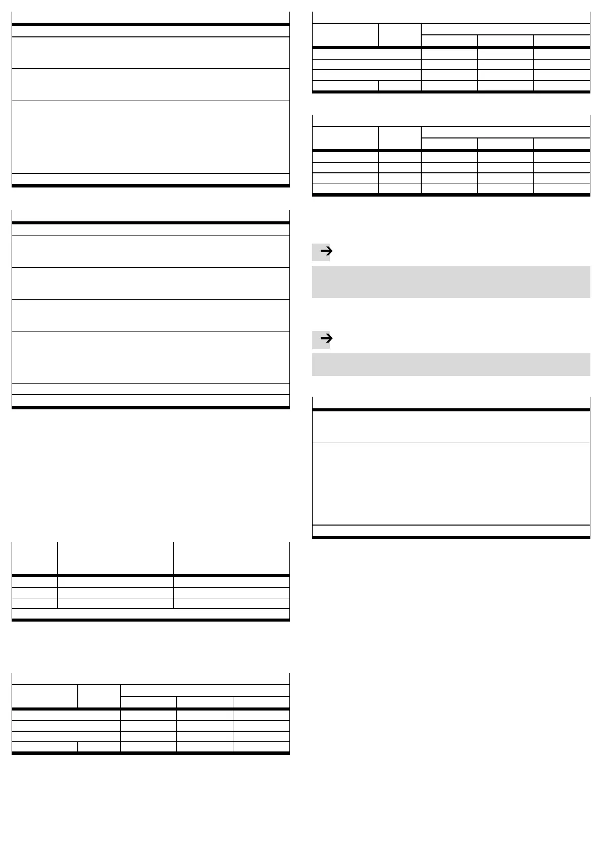
VPPM-...C1
Output pressure with
Signal 1 % FS
1)
Output pressure with
Signal
100 % FS
1)
2bartype 0.02 bar 2bar
6bartype 0.06 bar 6bar
10 bar type 0.1 bar 10 bar
1)
1) – FS = Full scale: 1 % FS = 0.1V or 4.16mA/100% FS = 10V or 20mA
– Output pressure: 0V or 4 mA creates an output pressure of 0 bar
Fig. 27
Select a suitable parameter set:
Recommended parameter sets VPPM-... Sizes 1/8”
Tube length
1)
Open sys-
tem
Output values in ml
0 ... 100 100 ... 1000 > 1000
0m 3 3 2 1
1m 3 3 2 2
3m 3 3 3 2
≥ 5m 3 3 3 2
1) With tubing inner diameter 6mm for 1/8” or 8mm for 1/4”
Fig. 28
Recommended parameter sets VPPM-... Sizes 1/4”
Tube length
1)
Open sys-
tem
Output values in ml
0 ... 500 500 ... 2000 > 2000
0m 3 1 2 3
1m 3 1 2 3
3m 3 2 3 3
≥ 5m 3 3 3 3
1) with tubing outer diameter 8mm or 10mm
Fig. 29
Recommended parameter sets VPPM-... s ize 1/2”
Tube length
1)
Open sys-
tem
Output values in ml
0 ... 2000 2000 ... 10000 >10000
0m 3 1 2 3
1m 3 1 2 3
3m 3 2 3 3
≥ 5m 3 3 3 3
1) with tubing outer diameter 12mm or 16mm
Fig. 30
7Operation
Note
When switching off the VPPM..., make sure that first the setpoint value is set
to 0 V or 4 mA, then the supply pressure, then the setpoint value and finally the
supply voltage are switched off.
Resetting the VPPM-...C1 to the factory setting
(also if the security code cannot be found)
Note
By resetting to fac tory settings, the current settings are lost.
• If required, make a note of these settings before resetting.
• Proceed as follows:
Reset the VPPM-...C1
1. Press and hold down the UP, DOWN and EDIT buttons.
2. Switch on the operating voltage.
3. Then release the buttons.
[ALL] flashes.
4. Select the parameters which you wish to reset to the factory setting with the
UP and DOWN buttons.
[Out] flashes: All output parameters are reset.
[In] flashes: All input parameters are reset.
[All] flashes: All input and output parameters as well as th e
security code are reset.
5. Press the EDIT button in order to reset the selected para meters.
The VPPM-...C1 is then in the RUN mode again.
Fig. 31
8 Service and maintenance
Cleaning:
• Switch off the following sources of energy before cleaning the exterior of the
device:
–Operatingvoltage
– Compressed air
• If the VPPM-...C1 is dirty, clean the exterior with a soft c loth.
The permitted c leaning agents are mild soapy water ( max. + 50 °C) or all non-
abrasive me dia.
9 Disassembly
Disassembling:
• Switch off the following sources of energy:
–Operatingvoltage
– Compressed air
• Disconnect the relevant connections on the VPPM-...C1.
• Remove the VPPM-...C1 from the fastening surface/hat rail.
10 Accessories
Accessories www.festo.com/catalogue
 Loading...