13 Accessories
The order numbers of the accessories and tools
can be found in the Festool catalogue or on the
Internet at "www.festool.com".
Use only original Festool accessories and
Festool consumable material intended for this
machine. These components are designed spe
cifically for this machine. Using accessories
and consumable material from other suppliers
will most likely affect the quality of your results
and limit warranty claims. Machine wear or
your own personal workload may increase de
pending on the application. Protect yourself and
your machine, and preserve your warranty
claims by always using original Festool acces
sories and Festool consumable material!
In addition to the accessories described,
Festool also provides a comprehensive range of
system accessories that allow you to use your
saw more effectively and in diverse applica
tions, e.g.:
• KA-KS60 trimming attachment
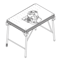
• UG-KAPEX KS 60 underframe
• UG-KS UNI underframe
• A-SYS-KS60 screw-in feet
• Clamping connection for MFT SZ-KS
• SM-KS60 bevel
13.1 Bevel
SM‑KS60 (available as an
accessory depending on the model)
The bevel can be used to gauge any angle (e.g.
between two walls). The bevel therefore forms
the angle bisection.
Gauging the interior angle [17A]
► Open the locking device [17-2]
.
► Swivel the router [17-1] out in order to
gauge the interior angle.
► Close the locking device.
The dashed mark [17-4] provides the angle bi
section. The angle bisection can be transferred
via the outside edges of the bevel to the position
markings
on the rotary base.
Gauging the exterior angle [17B]
► Open the locking device [17-2].
► Slide the aluminium profiles [17-3] on the
router forwards.
► Swivel the router [17-1] out so that the alu
minium profiles are at the exterior angle.
► Close the locking device.
► Slide the aluminium profiles for the two
routers back again.
Transferring the angle [18]
► Place the bevel perfectly in place on one of
the stop rulers
and press down with
your thumb.
► Release the rotary knob
.
► Hook in the detent lever .
► Swivel the rotary base , until the outside
edge of the bevel is congruent with the
marking .
To do so, the bevel must be positioned so
that it is parallel to the stop of the com
pound mitre saw. At the same time, apply
pressure to the stop ruler by pressing in
the recessed grip with your thumb.
English
27