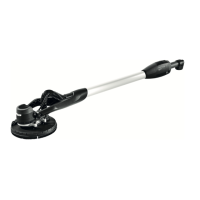
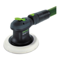
Long-reach sander LHS 2 225 EQI
Backing pad diameter 8-21/32" (220 mm)
Abrasive diameter 8-27/32" (225 mm)
Dust extraction con
nection
1-7/16" (1-1/16"),
36 mm (27 mm)
Frequency 2402 Mhz –
2480 Mhz
Equivalent Isotropically
Radiated Power (EIRP)
<10 dBm
Short version length
(without extension
tube)
47" (1.2 m)
Long version length
(one extension tube)
65" (1.65 m)
Weight as per EPTA-Procedure 01:2014
Long version (one ex
tension tube)
10.4 lbs (4.7 kg)
Short version (without
extension tube)
8.8 lbs (4 kg)
6 Functional description
[1-1]
Handle
[1-2]
Bluetooth
®
button
[1-3]
LED indicator
[1-4]
Surface control light button
[1-5]
On/off switch
[1-6]
T-handle
[1-7]
Hose clip
[1-8]
Handle
[1-9]
Speed control
[1-10]
Plug-it connection
[1-11]
Extractor connector
[1-12]
Suction sleeve stop
[1-13]
Locking lever
[1-14]
Extension tube
[1-15]
Suction regulator
[1-16]
Sanding head
[1-17]
Surface control light
[1-18]
Backing pad
[1-19]
Interface pad
[1-20]
Plug-it mains power cable
[1-21]
Insulated gripping surfaces
The pictures for the functional description are
on a fold-out page at the beginning of the in
struction manual. While reading the manual
you can fold out the page for comparison and
quick reference.
7 Commissioning
WARNING
Risk of injury, electric shock
► Always disconnect the mains plug from the
socket before performing any work on the
machine.
7.1 Assembling/disassembling
WARNING
Incorrect installation
Risk of injury from falling parts and loss of
control
► Before switching on the power tool, make
sure that all locking levers are completely
closed.
Assembly
[2]
The long-reach sander consists of a
LHS 2 225 EQI handle [1-1], a maximum of two
extension tubes EXT-LHS 2 225 [1-14] and a
sanding head TOP-LHS 2 225
[1-16].
►
Push the pipe end of the sanding head
into the opening on the handle as far as it
will go.
► Turn the locking lever [2-1] towards the
sanding head as far as it will go.
► Check whether the handle and sanding
head are firmly connected by pulling them
apart.
The handle and sanding head are securely con
nected.
Assemble the extension tubes in the same way
as the handle.
English
10

 Loading...