Bravo-Btava
W
)JTD
2000 range
Engine
Fuel feed system
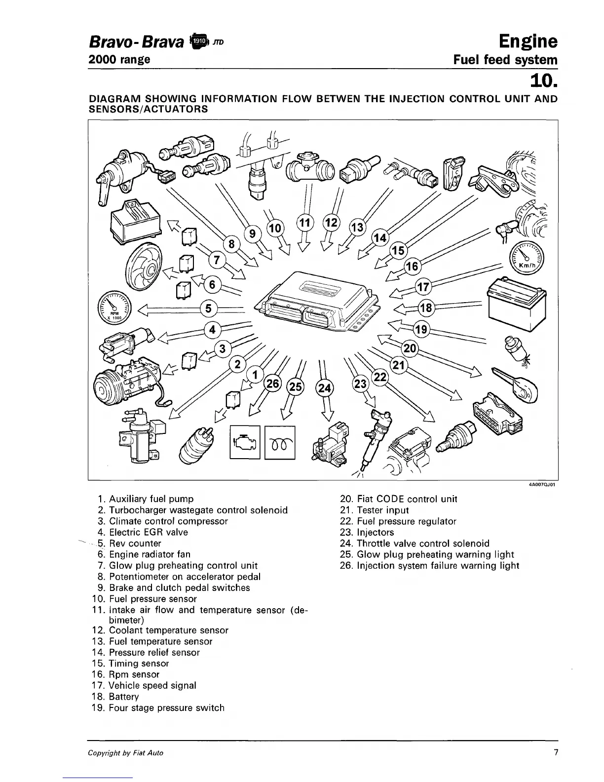
DIAGRAM SHOWING INFORMATION FLOW BETWEN THE INJECTION CONTROL UNIT AND
SENSORS/ACTUATORS
1.
Auxiliary fuel pump
2.
Turbocharger wastegate control solenoid
3. Climate control compressor
4.
Electric EGR valve
5. Rev counter
6. Engine radiator fan
7. Glow plug preheating control unit
8. Potentiometer on accelerator pedal
9. Brake and clutch pedal switches
10.
Fuel pressure sensor
11.
Intake air flow and temperature sensor (de-
bimeter)
12.
Coolant temperature sensor
13.
Fuel temperature sensor
14.
Pressure relief sensor
15.
Timing sensor
16.
Rpm sensor
17.
Vehicle speed signal
18.
Battery
19.
Four stage pressure switch
20.
Fiat CODE control unit
21.
Tester input
22.
Fuel pressure regulator
23.
Injectors
24.
Throttle valve control solenoid
25.
Glow plug preheating warning light
26.
Injection system failure warning light
Copyright by Fiat Auto
7
 Loading...