22
CHARGING
Different labels are used to ensure
compatibility between plug and socket.
The labels are attached to the inside
of the charging port flap of the vehicle.
Be sure to connect only cables of the
same type.
26 F1A0717
Symbol on the cable charging connector
(vehicle side) for Mode 2 and Mode 3
cables and on the charging port fl ap.
AC (alternating current) charging in the
home or at a charging station (≤ 480
V RMS).
27 F1A0725
Symbol on the cable charging
connector (charging station side) for
the Mode 3 cable and on the charging
station.
AC (alternating current) charging at a
charging station (≤ 480 V RMS).
28 F1A0718
Symbol on the cable charging
connector (vehicle side) for the Mode 4
cable and on the charging port flap.
DC (direct current) charging at a
charging station (50–500 V).
Before charging the high voltage
battery, it is recommended to turn the
ignition device to STOP in order to
obtain a charge until full in the shortest
period possible.
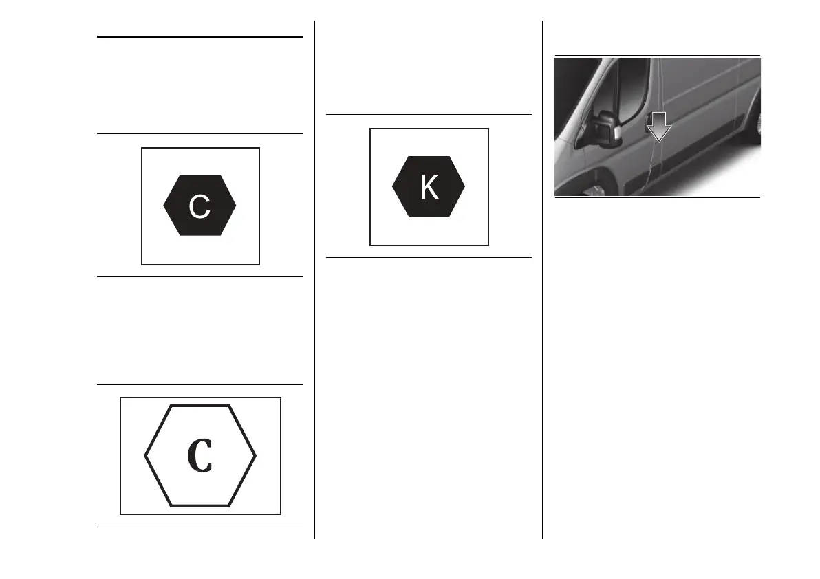
CHARGING PORT ON
THE VEHICLE
29 F1A1057
To access the charging port, open the
charging flap fig.29 by pressing on
the area indicated by the arrow.
CHARGING PORT LED
Next to the charging port there
are some LED (A) fig.30 or fig.31
(according to the versions) that
indicate the charging status by means
of four different colours and related
flashing types:
Blue: to indicate that the system is
waiting for a scheduled charging.
Green flashing: ("Flashing"):
during the charging process:
• one flashing green LED indicates
that charging is in progress;
• all 5 green LEDs flashing:
charging process initialisation;
 Loading...