2 - 14
AM35 Mainboard Manual
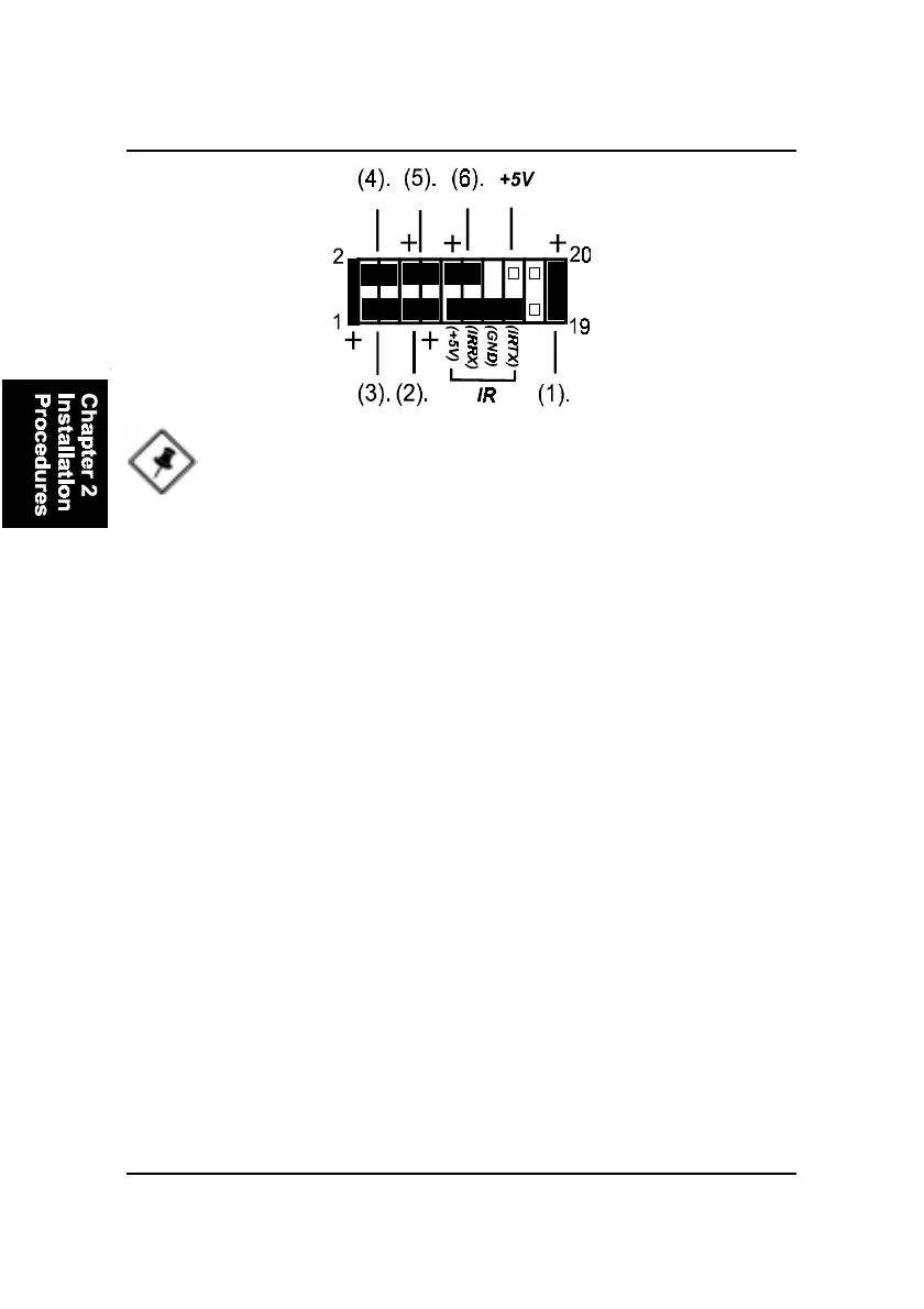
1. Power LED (2-Pin) is connected with the system power indicator to indicate
whether the system is on/off. It will blink when the system enters suspend
mode. There is a 3-Pin Power LED connector on board for some cases that with
a 3-pin plug.
2. Reset Button is connected to the reset button. Push this switch to reboot
the system instead of turning the power button off and on.
3. HDD LED is connected to the IDE device indicator. This LED will blink
when the hard disk drives are activated.
4. Dual Power LED it is in green light when the system in power on status.
It is in yellow light when the system in suspend mode.
5. Power Button is connected with power button. Push this switch allows the
system to be turned on and off rather than using the power supply button.
6. Suspend Button is connected with suspend button. To enter the system
into power saving mode, simply press this button when the system is in full-
on mode.
Speaker is connected with the case speaker.
NOTE: When a dual power LED is used, Pin 2 is for green one and
Pin 4 is for yellow one. If single power LED installed, Pin 2 is for
positive and Pin 4 is for negative.
IR is a 4-pin connector that is used for linking with your ID device to allow
transmission of data to another system that also supports the IR feature. An
IR module mounts to a small opening on system cases that support it.