CAUTION: READ AND FOLLOW ALL SAFETY GUIDELINES AND WARNINGS BEFORE HANDLING OR
ATTEMPTING ANY WORK ON YOUR FIELD ONE PAINTBALL MARKER. SHOULD YOU BE UNSURE AT ANY
POINT, STOP AND GET HELP FROM A FIELD ONE PAINTBALL CERTIFIED TECHNICIAN.
The Field One Nucleus engine was designed to give your Force
maximum reliability with minimal maintenance. The Nucleus engine
uses U-Cup directional seals along side traditional O-rings.
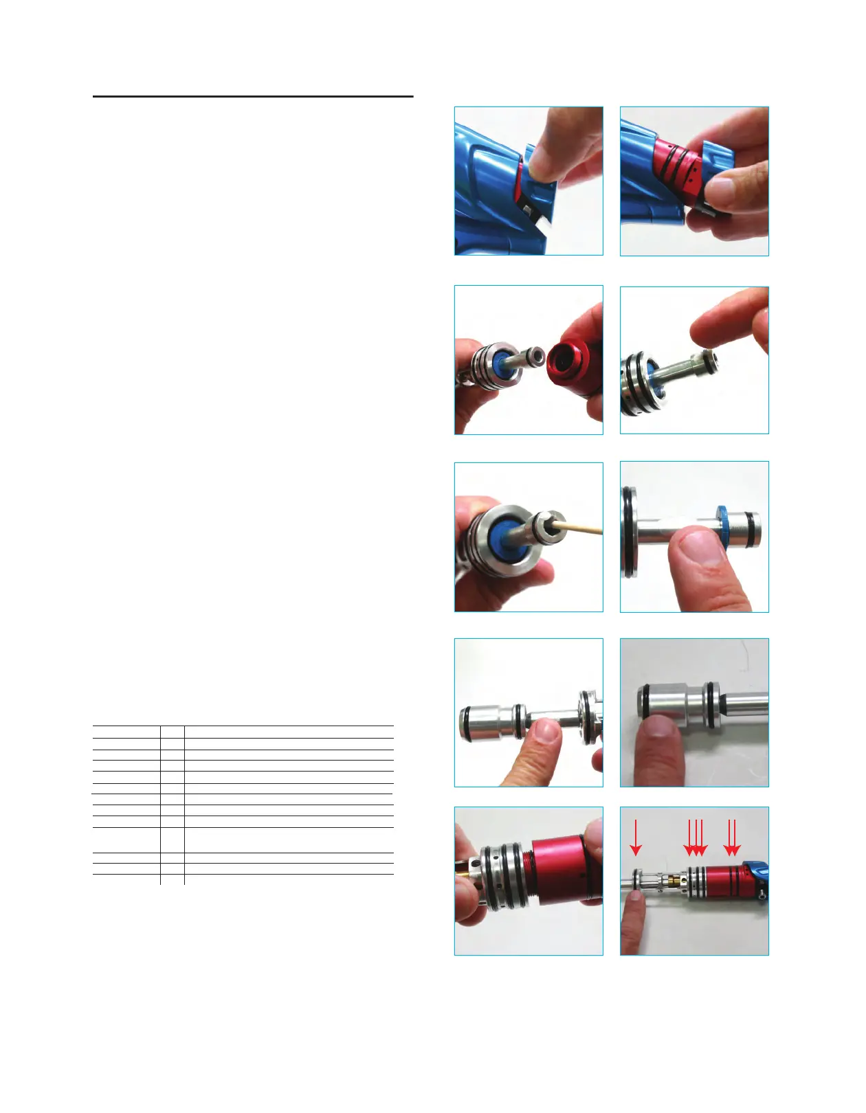
1) To remove the engine de-gas your marker and make sure there is
no pressure retained inside the marker. Pull up on the back cap
until it lifts away from the main body (fig 11A). If the cap does not
lift the gun may still be presurized. Empty the chamber by dry
fireing a shot in a safe location.
2) Pull the engine out towards the rear of the marker (fig 11B). Once
the engine is separated from the body you can separate the two
engine halves.
3) To seperate the engine halves unscrew the volume chamber from
the ram housing these parts should be tightly screwed together so
you may want to uses a towel to hold the volume chamber as you
twist. (fig 11C)
4) Apply grease to the.
• External Ram Shaft O-ring (U-cup 011) (fig 11D)
• Internal Ram Shaft O-ring (U-cup 009) (fig 11E). (You can
use a cotton swab r small allen wrench.)
• The ram shaft in front of the blue extension bumper. (fig 11F)
• The Bolt Stem.(fig 11G)
• A very light layer of grease on the bolt and bolt o-rings. (fig
11H) (if too much grease is applied here it may affect eye
performance).
5) When rejoining the two engine halves, be sure to tighen them
togather to insure a tight fit. (fig 11I)
6) Add a small amout of grease to the static o-rings around the
outside of the engine to insure a smooth re-entry. (fig 11J)
7) To reinstall your engine make sure the back cap is in the up
posintin and gently slide the engine back into the marker.
8) Once it is completely inserted push down on the back cap untill it
snaps into place.
You do not need to change any of the seals unless there is an
obvious leak or fault in performance. When troubleshooting always
make sure your air tank has adaquire pressure and is screwed into
the ASA completely and the cam drive knob is fully engaged. Make
sure the marker has fresh batteries. Please consult the complete
manual at fieldonepaintball.com for trobleshooting guide ad FAQ.
Engine O-ring Index
(fig 11A) (fig 11B)
(fig 11C) (fig 11D)
(fig 11E) (fig 11F)
(fig 11G) (fig 11H)
(fig 11I) (fig 11J)
O ring 1x3
O ring 1x2
O ring 021
O ring 021
U Cup 009
O ring 020
U Cup 110
O ring 017
U Cup 011
U Cup 011
O ring 011
O ring 015
O ring 1x15
2
1
2
3
1
1
1
2
1
2
1
2
1
Back Block Detent Plunger
Reduction Shaft to Ram Housing
Outside Ram Housing
Outside Volume Chamber Rear
Inside Ram (opening faces front)
Outside Volume Chamber Front
Front of Volume Chamber (opening faces back)
Inside Volume Chamber Outside Brass Shut Off
Back of Ram (opening faces front)
Inside Brass Shut Off
(openings face away from eachother)
Inside Front Brass Shut Off
Outside Bolt
In between Engine Halfs
FORCE ENGINE MAINTENANCE
 Loading...