CAUTION: READ AND FOLLOW ALL SAFETY GUIDELINES AND WARNINGS BEFORE HANDLING OR
ATTEMPTING ANY WORK ON YOUR FIELD ONE PAINTBALL MARKER. SHOULD YOU BE UNSURE AT ANY
POINT, STOP AND GET HELP FROM A FIELD ONE PAINTBALL CERTIFIED TECHNICIAN.
(fig 11K) (fig 11L)
(fig 11M) (fig 11N)
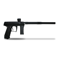
Removing the bolt from the ram is not part of general maintenance,
but may be necessary for troubleshooting. To remove the bolt from
the ram:
1) Separate the two engine halves. (fig 11C)
2) Insert a 7/32 allen wrench into the rear of the ram.(fig 11K)
3) Grip the bolt with a towel and turn the wrench to loosen the ram
shaft from the bolt stem. (fig 11K) If you are unable to separate the
parts in this way use a vice grips and a piece of rubber hose to grip
the bolt head.(fig 11L)
4) Once the parts are separated you can perform the necessary
maintenance.
5) Reinstall the ram shaft by putting the blue extension bumper on
the ram, (fig 11M) and re inserting the ram shaft into the shut off
and volume chamber. (fig 11N)
6) Use the 7/32 allen wrench to tighten the ram back onto the bolt.
Grip the bolt with a towel to ensure a snug fit.
7) Tightly screw Engine halves back together. (fig 11I)
021
015 020
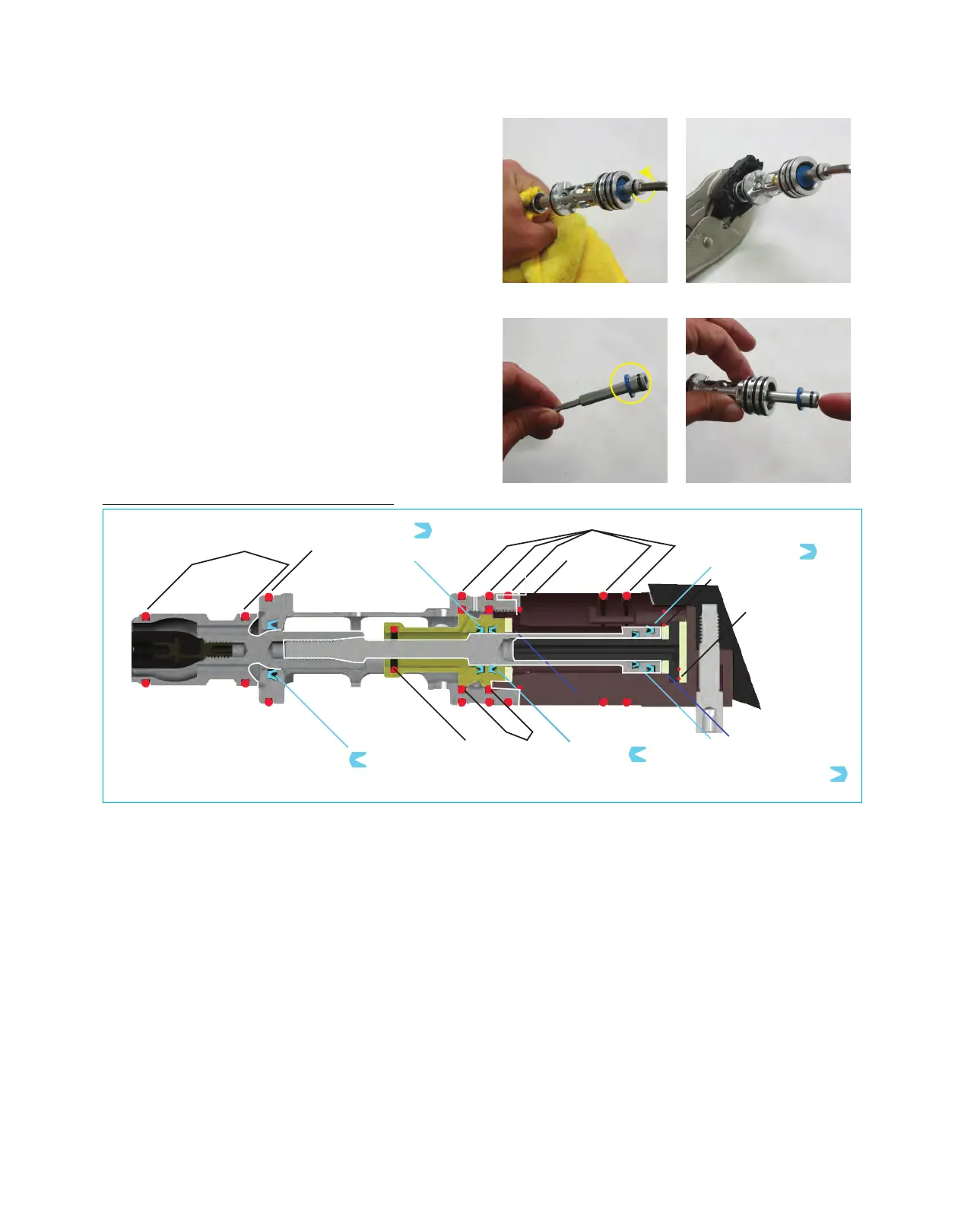
U-CUP 110
opening faces rear
011 017
U- Cup 011
Opening faces rear
U- Cup 009
opening faces front
U- Cup 011
Opening faces front
U- Cup 011
Opening faces front
Ram extention
bumper
Ram retraction
bumper
1x15
1x2
1x3
Force Engine Cross Section and O-ring Placement
(fig 11O)