1716
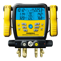
MicroAmps DC (µADC)
Test flame rectifier diodes on a heater control. Connect leads between
flame sensor probe and control module. Turn heating unit on. When the
flame is on, there should be a measurable µADC signal, typically under
10µADC. Compare measurement to manufacturer’s specification to
determine if replacement is necessary.
Ranges: 1000µA Resolution: 0.1µA
Accuracy: ±(1.0% + 5) Volts burden: 5V
Overload Protection: 600VDC or 600VAC rms
Frequency (Hz) Through Leads
Check incoming voltages to ensure they are cycling at 60Hz. For
frequency measurements on VFD equipment, use the amp clamp.
Ranges: 100Hz, 1000Hz, 10kHz, 100kHz, 1000kHz Resolution: 0.01Hz
Accuracy: ±(0.1% + 5) Sensitivity: 10Hz to 1000kHz: >3.5Vrms
Minimum PW: >1µs Duty Cycle Limits: >30% and <70%
Overload Protection: 600VDC or 600VAC rms
Duty Cycle (%)
Duty cycle shows the % On Time of a 5V logic signal square wave.
Ranges: 5%-95% (40Hz to 1kHz), 10%-90% (1kHz to 10kHz), 20%-80%
(10kHz to 20kHz)
Accuracy (5V logic): ±(2% + 10) Resolution: 0.1%
Pulse Width: >10µs
Overload Protection: 600VDC or 600VAC rms
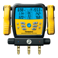
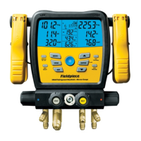
Capacitance (MFD)
Test motor start and run capacitors. Capacitors are one of the most
failure prone components in a HVACR system. Disconnect from power and
any resistors found between terminals. Discharge capacitor before testing. If
dIS.C is displayed, the capacitor needs to be fully discharged to test.
Ranges: 10nF, 100nF, 1000nF, 10µF, 100µF, 1000µF, 10mF
Accuracy: ±(3% + 15) 10nF, ±(3% + 5) 100nF to 1000µF, ±(5% + 5) 10mF
Resolution: 0.01nF Overload Protection: 600VDC or 600VAC rms
Discharge Cap First!