How to proceed: Step by
step mounting the AKAS®
1a. Overrun Traverse
Measurement
1b. adjustment of the dip
switches
only AKAS®-3...
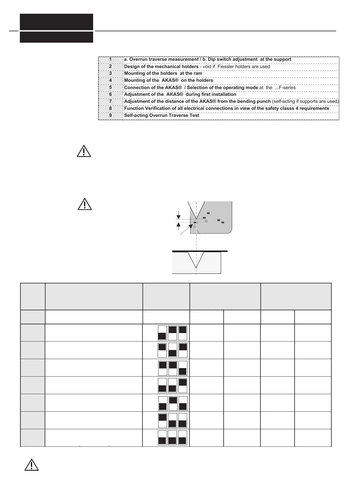
table 15/1
The press must have an automated overrun traverse control for the first stroke. If not, it can be realised by
the AKAS®-...F and a cam controller or by the Fiessler AMS-system . Before the initial start-up, the overrun tra-
verse must be checked either by using the test rod (see page 9) or by using an Overrun Traverse measuring
device. (upon customer's request, Fiessler Elektronik will perform the Overrun Traverse Measuring on the customer's machine.)
If the results of 10 consecutive measurements are larger than 11mm (AKAS®-3P...,) the fast speed must be re-
duced.
According to the induvidual overrun traverses of each machine, 7 different distances Z
(=gap between uppermost receiver ele-
ment and bending punch, see Fig. 15/1 u. Fig. 15/2)
can be programmed via 3 dis switches at the support. The adjustment to the re-
spective selected distance is carried out automatically. (s. chapter 5.7 (Adjustment of the distance of the AKAS® from
the bending punch). Fiessler delivers the system pre-adjusted "B".
Mounting
5
How to proceed when mounting the AKAS®
Overrun Traverse Measurement / According dip switch adjustment
E1
Z
Fig.15/1
Mark
* by this, a tolerance in
sheet metal waviness
of about 2mm is given.
B 11 mm 14 mm 19 mm
C
D
9 mm
8 mm
12 mm
11mm
17 mm
16mm
E
F
G
H
7 mm
6 mm
5 mm
4 mm
10mm
9mm
15mm
14mm
8mm
7mm
13mm
12mm
6 mm 19 mm
4 mm
3mm
17 mm
16mm
0mm
0mm
15mm
14mm
0mm
0mm
13mm
12mm
distance Z after completed automatical adjust-
ment in accordance to the max. allowable
overrun traverse of the press brake after the
interruption of the beams. AKAS®-3P...
recommended blanking point
SP->1 above the slug surface
AKAS®-3P...
recommended change-over point
(V->10mm/s) from fast speed into
slow speed* above the slug
surface *AKAS®-3P...
The distance must not be less than the
stopping distance of the machine
flat (HUSP=0) box (HUSP=1)
flat (HUSP=0) box (HUSP=1)
FIESSLER
E L E K T R O N I K
The adjustment A is not applicable for AKAS 3P.
1 a. Overrun traverse measurement / b. Dip switch adjustment at the support
2
3
Design of the mechanical holders - void if Fiessler holders are used
Mounting of the holders at the ram
4
5
6
7
Mounting of the AKAS® on the holders
Connection of the AKAS® / Selection of the operating mode at the ...F-series
Adjustment of the AKAS® during first installation
Adjustment of the distance of the AKAS® from the bending punch (self-acting if supports are used)
8
9
Function Verification of all electrical connections in view of the safety classs 4 requirements
Self-acting Overrun Traverse Test
The distance to the upper tool must be set so
that the A-test with the test block is passed.
Doku Nr. 1379 Stand 27.1.2017 /Aui
 Loading...