1.For the first adjustment or after a tool change the key operated switch at
the support of the receiver must be turned to "ON", if the foot pedal is not
activated.
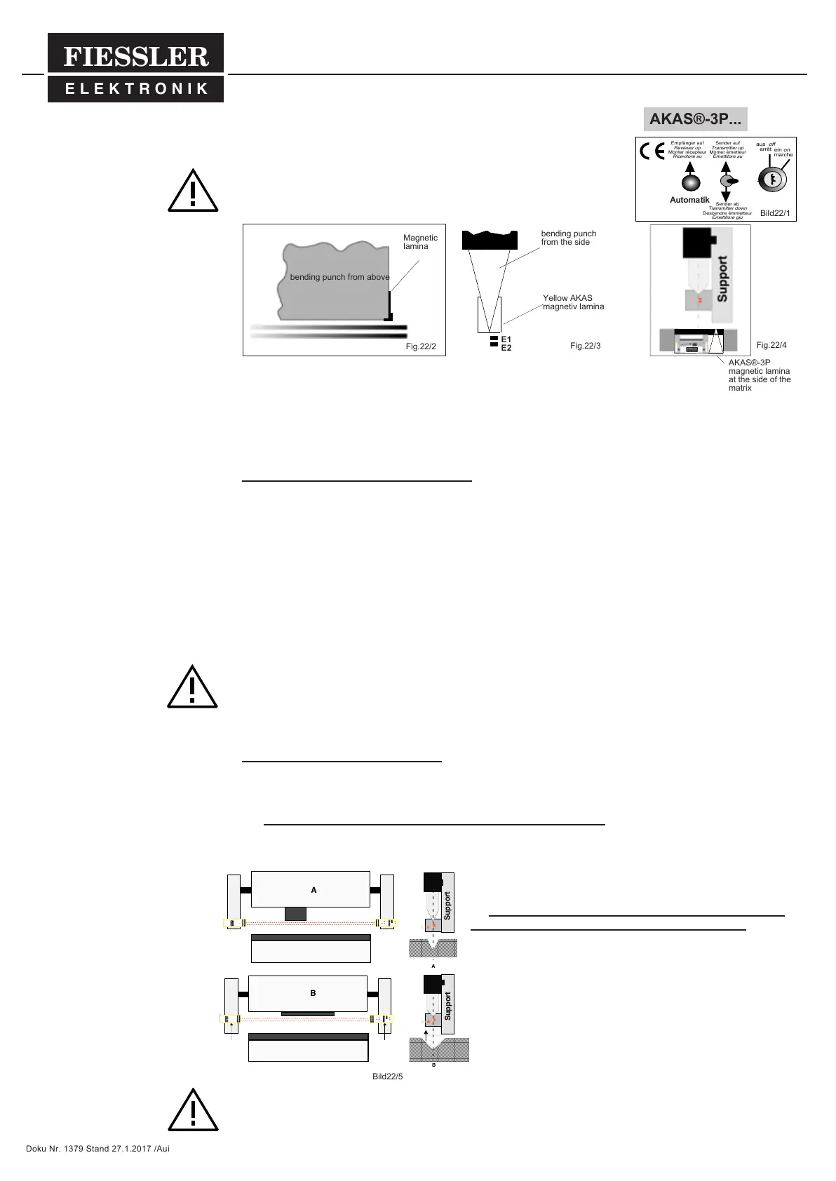
2 .Attach the yellow magnetic lamina vertical at the bending punch so that its
edge is even with the bending punch. A correct adjustment is only possible
if the magnetic lamina is even with the bending punch, as shown in fig. 22/3.
After having sucessfully adjusted the AKAS® system, place the bigger magnetic lamina
at the side of the matrix (as shown in fig. 22/4) in order to cover it. It must be attached in a way
that its edge is even with the matrix surface.
During the whole operation, the magnetic lamina must remain at the side of the
matrix in order to cover it.
3. Now, the operator may choose from 2 different adjustment modes:
A. Automatic adjustment (Automatic Mode):
By pushing ONCE the button "Automatik" this adjustment mode is started. The procedure is automatically stop-
ped as soon as the AKAS® system has reached the correct distance beneath the bending punch. The automa-
ted adjustment procedure can be interrupted, if - during the downward movement of both the AKAS®-transmitter
and the AKAS®-receiver - the switch =transmitter up is activated. (This action will be of help primarily in the
case of a large tool being exchanged by a considerably smaller tool.) By doing this, the downward movement of
the transmitter and receiver towards the lowest point is prevented or stopped. If the transmitting light beam hits
the receiver elements, i.e. the optics of both components are "locked into one another" (focussing), the AKAS®
system will adjust itself automatically onto the exchanged tool newly fixed at the ram. If the light beam from the
transmitter does not hit the receiver (i.e. the transmitter beams are interrupted by the newly mounted tool), both
transmitter and receiver will move downward to the lowest point of the displacing range. When moving upwards
again, they are searching the lower edge of the bending punch. The system will automatically adjust itself to the
newly installed bending punch.
After having carried out this, the key at the key-operated switch is turned to "OF"F and the key is removed from
its lock.
After having completed the adjustment procedure, the tests (see page 9) must be carried out. If the key
of the key-operated switch is removed from its lock, the outputs of the system are free only if the " Auto-
mated Mode" has been competely terminated.
B. Adjusting by hand (Manual Mode):
By activating the button "transmitter down" the manual adjustment mode is started. Now the operator must
check if either the transmitter beam hits the receiver : - adjustment indicators P do not light up (see B1) -
or if the transmitter beam does not hit the receiver - adjustment indicators P light up (see B2)
B1: (This function is required during the first adjusting of the system)
AKAS®-II-transmitter and AKAS®-receiver can be carried upwards or downwards by activating the switch "rans-
mitter up / down". This is to verify whether both transmitter and re-
ceiver are correctly mounted parallel to the bending line of the
machine. By activating the "Automatik"-button, the operator may
start the automated adjusting procedure.
B2:(This function is carried out if the transmitter beam does
NOT hit the receiver, p.e. if high matrixes are used)
By activating the "Automatik"-button or the "receiver up"-button,
the receiver is carried upwards. At the same time, the transmitter
can be carried upwards by activating the switch ="ransmitter up/
down". As soon as the transmitter beam hits the receiver again -
adjustment indicators P are out at the receiver-, the adjusting
procedure can be terminated as described in the automated ad-
justment "Automatic Mode" A.).
If the key of the key-operated switch is removed from its
lock, the outputs of the system are free only if the " Automa-
ted Mode" has been competely terminated. The key switch
must not be turned, if the foot pedal is activated. The key must be kept under the control of a responsi-
ble person (set-up man)!
Mounting
adjustment directions - after tool change
adjustment directions
You will find these adjustment
directions also on the from plate
pof the receiver support!
The magnetc lamina has to be
placed a s close as possible to
the receiver side! Like displayed
on the magnet lamina.
Schematic layout of the
AKAS®-II after a tool change-
over and of the consecutive
follow-up of the transmitter and
the receiver.
5
5.8
Empfänger auf
Reviever up
Monter récepteur
Ricevitore su
aus off
arrêt
Sender auf
Transmitter up
Monter émetteur
Emettitore su
Sender ab
Transmitter down
Descendre émmetteur
Emettitore giu
ein on
marche
Fig.22/2
Magnetic
lamina
A
B
A
B
Support
Support
E3
E2
E1
E3
E2
E1
FIESSLE
R
E L E K T R O N I K
FIESSLE
R
E L E K T R O N I K
FIESSLE
R
E L E K T R O N I K
FIESSLE
R
E L E K T R O N I K
Fig.22/3
bending punch
from the side
Bild22/5
Bild22/1
bending punch from above
AKAS®-3P...
FIESSLER
E L E K T R O N I K
AKAS®-3P
magnetic lamina
at the side of the
matrix
Fig.22/4
E1
Yellow AKAS
magnetiv lamina
Doku Nr. 1379 Stand 27.1.2017 /Aui