Electrical connections - Description / Wiring diagrams
6
-with selectable safety functions
6.4
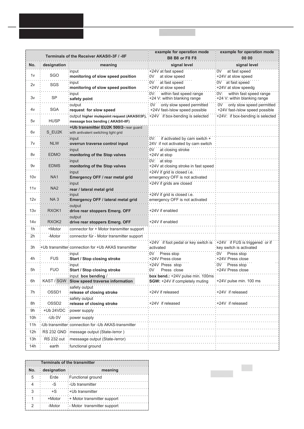
Terminals of the Receiver AKAS®-3F / -IIF
example for operation mode
B8 B8 or F8 F8
example for operation mode
00 00
No.
1v
designation
SGO
meaning
input
monitoring of slow speed position
+24V at fast speed
0V at slow speed
0V at fast speed
+24V at slow speed
input
monitoring of slow speed position
output
request for slow speed
output higher mutepoint request (AKAS®3F),
message box bending ( AKAS®-IIF)
0V at fast speed
+24V at slow speed
0V: within fast speed range
+24 V: within blanking range
0V at fast speed
+24V at slow speedg
0V: within fast speed range
+24 V: within blanking range
0V only slow speed permitted
+24V fast-/slow speed possible
+24V if box-bending is selected
0V only slow speed permitted
+24V fast-/slow speed possible
+24V: if box-bending is selected
+Ub transmitter EU2K 500/2- rear guard
with antivalent switching light grid
input
overrun traverse control input
input
monitoring of the Stop valves
input
monitoring of the Stop valves
input
Emergency OFF / rear metal grid
input
rear / lateral metal grid
input
Emergency OFF / lateral metal grid
output
drive rear stoppers Emerg. OFF
0V: if activated by cam switch +
24V if not activated by cam switch
0V at closing stroke
+24V at stop
0V: at stop
+24V at closing stroke in fast speed
+24V if grid is closed i.e.
emergency OFF is not activated
+24V if grid is closed i.e.
emergency OFF is not activated
+24V if enabled
14v
1h
2h
3h
RXOK2
+Motor
output
drive rear stoppers Emerg. OFF
connector for + Motor transmitter support
-Motor
connector für - Motor transmitter support
connection for +Ub AKAS transmitter
4h
5h
6h
7h
FUS
FUO
input
Start / Stop closing stroke
input
Start / Stop closing stroke
input box bending /
Slow speed traverse information
safety output
release of closing stroke
+24V if foot pedal or key switch is
activated
+24V if FUS is triggered or if
key switch is activated
0V Press stop
+24V Press close
+24V Press stop
0V Press close
0V Press stop
+24V Press close
0V Press stop
+24V Press close
box bend.: +24V pulse min. 100ms
SGW: +24V if completely muting
+24V if released
+24V pulse min. 100 ms
+24V if released
8h
9h
10h
11h
OSSD2
+Ub 24VDC
safety output
release of closing stroke
power supply
connection for -Ub AKAS-transmitter
12h
13h
14h
RS 232 GND
RS 232 out
message output (State-/error )
messaage output (State-/error)
earth functional ground
+24V if released +24V if released
Terminals of the transmitter
No.
5
designation
Erde
meaning
Functional ground
4
3
1
2
-S
+S
-Ub transmitter
+Ub transmitter
+Motor
-Motor
+ Motor transmitter support
- Motor transmitter support
inputs
switching
antivalent
inputs
switching
equivalent
inputs
switching
antivalent
inputs
switching
equiva-
lent
FIESSLER
E L E K T R O N I K
The using of the grey
shaded connections
depends on the closed
type (look page 36/37)
Doku Nr. 1379 Stand 27.1.2017 /Aui
 Loading...