This Meter defaults in the autoranging mode and displays
V, AC and AUTO. AUTO (autoranging) is applied to the bar
graph.
To measure voltage, connect this Meter in parallel with the
load or circuit under test. Each of the three AC/DC voltage
ranges presents an input impedance of approximately 10
MΩ in parallel with less than 100pF.
Measurement errors due to circuit loading can result when
making either AC or DC voltage measurement on circuits
with high source impedance. In most cases, the error is
negligible (0.1% or less) if the measurement circuit source
impedance is 10 Kilohms or less.
5.9 Measuring Resistance
Press the Ω pushbutton to enable the re
s
i
s
tance
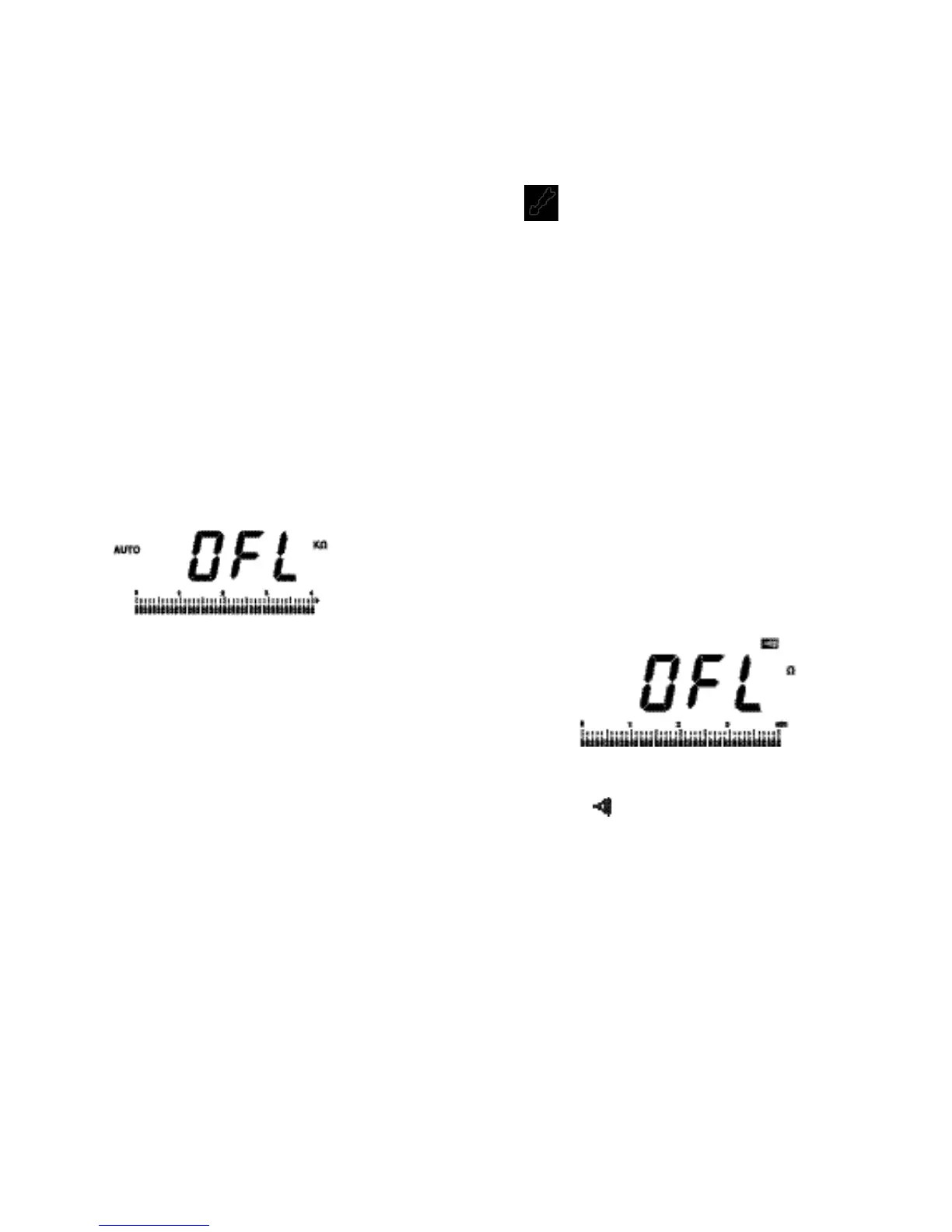
measurement mode. This Meter defaults in the autoranging
mode and displays KΩ and AUTO. And also the off-scale
arrow of the bar graph blinks and the digital display reads
OFL.
AUTO (autoranging) is applied to the bar graph.
This Meter measures resistance by comparing the internal
reference resistance given by a resistor array with the
unknown resistance to be measured. Remember, the
resistance displayed by this Meter is the total resistance
through a
l
l possible paths between the probes. This
explains why in-circuit measurement of resistors does not
often yield the ohms value indicated by the resistor’s color
code.
1514
CAUTION!
TURN OFF POWER ON THE TEST CIRCUIT AND
DISCHARGE ALL CAPACITORS BEFORE ATTEMPTING
INCIRCUIT RESISTANCE MEASUREMENTS. IF AN
EXTERNAL VOLTAGE IS PRESENT ACROSS A
COMPONENT, IT WILL BE IMPOSSIBLE TO TAKE AN
ACCURATE MEASUREMENT OF THE RESISTANCE OF
THAT COMPONENT.
The resistance in the test leads can diminish accuracy on
the lowest (400-ohm) range. The error is usually 0.1 to 0.2
ohms for a standard pair of test leads.
When measuring resistance, be sure that the contact
between the probes and the circuit under test is good. Dirt,
Oil, Solder flux, or other foreign matter seriously affect
resistance.
5.10 Continuity Testing
Press the pushbutton to enable the continu
i
ty testing
mode. This Meter defaults in the 400-ohm range and then
highest bar graph scale shows 400. The digital displa
y
reads OFL.
Continuity testing verifies that circuit connections are intact.
Test resistances below 35Ω cause the Meter to emit a
continuous tone.
 Loading...