Follow these steps to check a diode.
1. Set the Function switch to the “ ” position.
2. Insert the black test lead into the “COM” input terminal and the
red test lead into the “VΩHz CAP” input terminal.
3. Touch the red test lead to the Anode ( + side, non-banded end )
and the black test lead to the Cathode ( – side, banded end ).
4. If the diode is good, the reading should indicate 0.3V to 0.8V on
the LCD.
5. Reverse the red and black leads on the diode, if the LCD reads
O.F.L
(the overload sign), the diode is good.
NOTE: A defective diode will read
O.F.L
(the overload sign) or
0.00 no matter how the test leads are connected.
4.3.3. Microwave Diodes
Most microwave diodes can not be tested by a DMM with a diode
test function. This is be
c
ause the DMM does not supply enough
power to turn these diodes on. We offer an accessory test lead,
model TL60, that boosts the power output so that microwave
diodes can be adequately tested. Consult your distributor for more
details.
4.4. Measuring Current (Amps)
CAUTION!
THE CURRENT FUNCTIONS ARE PROTECTED BY A FUSE OF
600 VOLT RATING. TO AVOID DAMAGE TO THE
INSTRUMENT, CURRENT SOURCES HAVING OPEN CIRCUIT
VOLTAGES GREATER THAN 600 VOLTS DC OR AC MUST
NOT BE MEASURED.
26 27
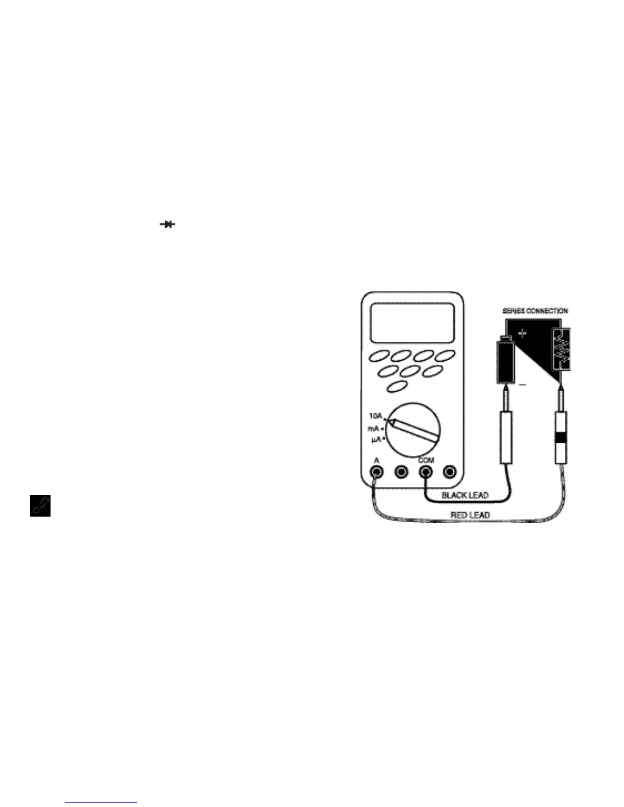
NOTE: When taking current measurements, this Meter must
be connected in SERIES with the circuit (or circuit
element) under test. NEVER CONNECT THE TEST
LEADS
A
CROSS A VOLTAGE SOURCE while the
rotary switch is set to Amps. This can cause damage
to the circuit under test or this Meter.
• To measure current, you must break the circuit and connect the
test leads to two circuit connection points. The connection must
be in series with the current.
 Loading...