4.3 Continuity Test, Diode Test and Microwave Diodes
4.3.1 Continuity Test
Th
i
s
mode helps you check electrical circuits, su
c
h as wiring,
speaker cables, connections, switchers, or relays for short or open
circuits. In cont
i
nuity test, a measured value of approx. 100Ω or
less causes the Meter to emit a continuous tone.
Follow these steps to check continuity.
1. Set the Function switch to the “ ” position.
2. Insert the black test lead into the “COM” input terminal and the
red test lead into the “VΩHz CAP” input terminal.
3. Connect the test leads to the circuit to be measured.
4. Th
i
s Meter will emit a continuous tone for resistance of less
than 100 ohms.
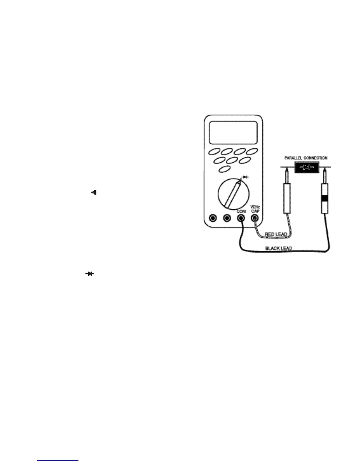
4.3.2. Diode Test
Diode test lets you check diodes, transistors, and other
semiconductors for opens, shorts, and normal operation. NEVER
CONNECT THE TEST LEADS TO A SOU
R
CE OF VOLTAGE
when the rotary switch is set to .
• In diode test, drop voltage in the forward direction is displayed
when diode is connected in the forward direction.
For a germanium diode, the typical forward voltage is about
0.4V and in case of a silicon diode, about 0.6V.
• Judge the semiconductor device as follows:
If the digital reading in one direction shows a value and the
reading in reverse direction shows an overload (
O . F . L
), the
device is good.
If the digital reading is the same in both directions, the device is
probably shorted.
If the display reads
O . F . L
in both directions, the device is
probably open.
24 25
 Loading...