• When measuring large resistance, reading may be unstable due
to environmentally induced electrical noise. In this case, directly
connect the resistor to input terminals of the Meter or shield the
resistor at potential of the COM input terminal to obtain stable
reading.
• For resistance abo
v
e 1 Megohm, the display may take a few
seconds to stabilize. This is normal for high-resistance readings.
• The Meter has a circuit to protect the resistance range from
over-voltage (600V AC). However, to prevent accidentally
exceeding the protection circuit’s rating and to ensure a correct
measurement, NEVER CONNECT THE TEST LEADS TO A
SOURCE OF VOLTAGE when the rotary switch is set to Ω or
or functions.
22 23
• The current applied during re
s
i
s
tance measurements could
damage some devices. The table below lists the test voltage
and current available for each resistance measurement range.
(All values are typical.)
NOTE: (A) is the open circuit test voltage at the input
terminals in volts.
(B) is the voltage drop across a resistance equal to full
scale value.
(C) is the current through a short circuit at the input
terminal.
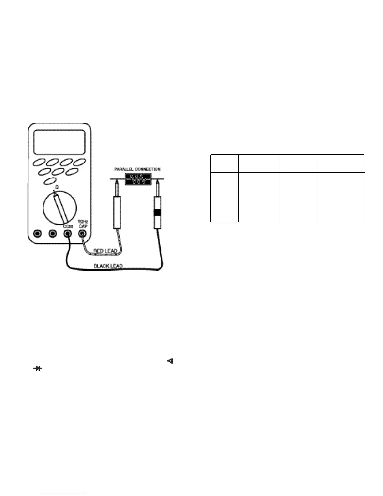
4.2.1 Measuring Resistance (Ohms)
When measuring resistance, be sure that the contact between the
test leads and the circuit under test is good. Dirt, oil, solder flux, or
other foreign matter seriously affect the reading value.
Follow these steps to measure ohms.
1. Set the Function switch to the desired “Ω” position.
2. Insert the black test lead into the “COM” input terminal and the
red test lead into the “VΩHz CAP” input terminal.
3. Connect the test leads to the circuit to be measured.
4. The measured resistance will be displayed on the LCD.
RANGE OPEN CIRCUIT FULL SCALE SHORT CIRCUIT
VOLTAGE (A) VOLTAGE (B) CURRENT (C)
400 Ω < 200 mV
< 740 µA
4 KΩ < 320 mV < 60 µA
40 KΩ < 1.2 V < 340 mV < 11 µA
400 KΩ < 340 mV < 1.5 µA
4 MΩ < 340 mV < 0.2 µA
40 MΩ < 1mV < 0.2 µA
 Loading...