Follow these steps to measure capacitance.
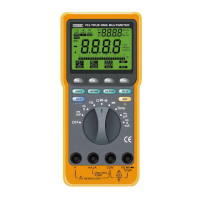
1. Insert the test leads into the input terminals.
2. Set the rotary switch to the “CAP” position.
3. Touch the probes to the capacitor and read the display.
When measuring po
l
arized capacitor
s
, connect the positive to
the VΩHz CAP terminal and the negative to the COM terminal.
Capacitor dielectric absorption can cause measurement errors.
If more discharge is necessary, the Meter displays “ ”
while the capacitor is discharging.
• In capacitance, the Meter is
always autoranging.
•
In 1µF range, the readings are
probably unstable due to
environmentally induced
electrical no
i
s
e and floating
capacity of the test leads.
Therefore, directly connect the
object to be measured to the
input terminals.
• Bar graph does not function in
capacitance mode.
32
33
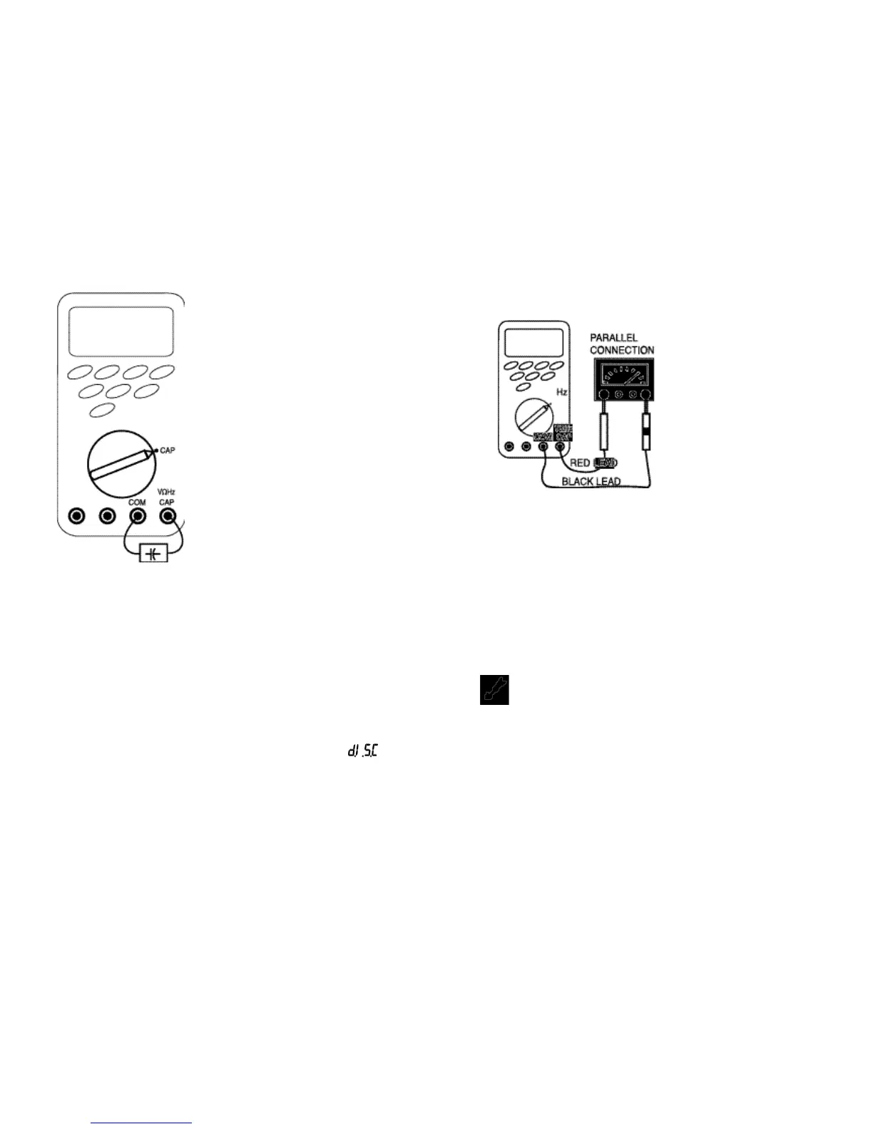
PARALLEL CONNECTION
4.7 Measuring Frequency
Follow these steps to measure frequency.
1. Insert the test leads in the input terminals.
2. Set the rotary switch to the “Hz” position.
3. Touch the probes to the test points, and read the display.
If the measured frequency is greater than 200 KHz, “
O . F . L
”
(overload) is displayed.
4.8 Measuring Temperature
WARNING!
DO NOT ALLOW TEMPERATURE PROBES TO CONTACT ANY
LIVE VOLTAGE THAT MAY EXCEED 30 AC V RMS OR 42 AC V
PEAK OR 60 DC V. UNPLUG TEMPERATURE PROBE BEFORE
TAKING MEASUREMENTS OTHER THAN TEMPERATURE.
INSTRUMENT AND/OR EQUIPMENT DAMAGE COULD
RESULT IF THE ABOVE WARNINGS ARE NOT FOLLOWED.
• In frequen
c
y, the Meter is
always autoranging.
• When disconnecting the
i
nput terminals, the
o
v
erload sign ma
y
be
displayed or the display
may unsteadi
l
y fluctuate.
This is typical.
• Bar graph function
s
in
frequency measurement.
 Loading...