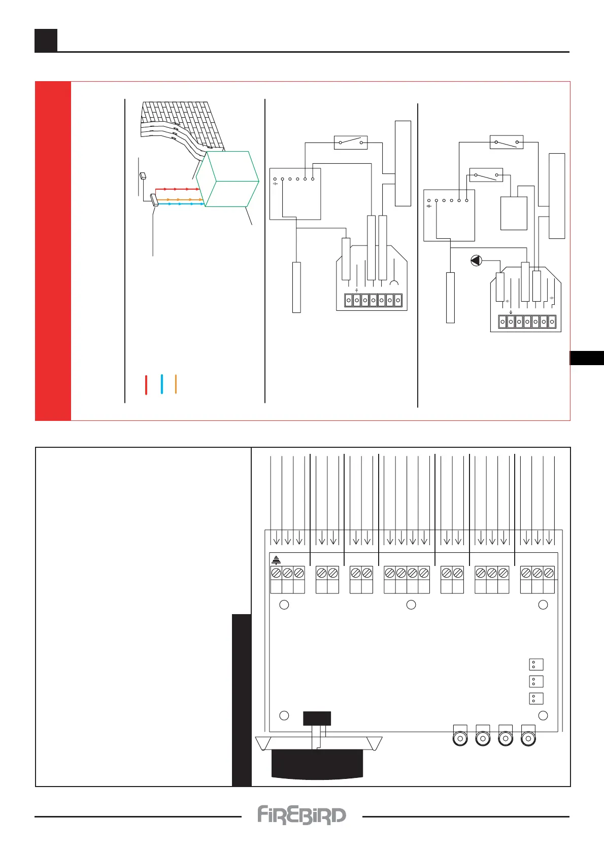
1. Permanent Live To Combi
2. Switch Live For Domestic Hot
3. Switch Live For Central Heating.
Important Re: Wiring Combi Boiler
When connecting the Combi to a remote single channel timer,or programmable room stat,
or a two gang timer, follow instructions shown in diagrams below.
The Permanent Live to a Combi is needed for an over heat thermostat,
and for a Frost Thermostat in the case of the Firebird Combi Pac.
Make sure that the permanent live is connected to the
'mains in' plug and is protected by a 5 Amp. Fuse.
Heat Resistant Cable must be used when connecting
power supply to, and from this boiler.
Remote Timer
Mains Supply
Firebird
Combi Pac
Boiler
2.
3.
1.
Mains Plug Wiring for
Combi and Combipac.
Mains Plug Wiring for Kitchen Utility,
Heatpac & System Boilers.
Use Heat
Resistant Cable
Protect Supply
With 5 Amp fuse.
Permanent Live.
Earth.
Neutral.
Mains Plug
L1 N T1 L2 S3 B4
Switch Live
Earth.
Neutral.
Mains Power Supply
MV.
Refer to
manafacturers
instruction
Tank
Stat.
Zone Valve.
Refer to manafacturers instruction
Two Wire
Volt Free
Room Stat.
System Programmer.
DHW.
CH.
Neutral.
Pump Live
Zone Valve.
Refer to manafacturers instruction
Two Wire
Volt Free
Room Stat.
System Programmer.
DHW.
CH.
Neutral.
Mains Power Supply
Combi
Mains Plug
Permanent Live.
Earth.
Neutral.
L1 N T1 L2 S3 B4
Hot Water Switch Live
Room Stat
Heating Timer Switch Live
Use Heat
Resistant Cable
Protect Supply
With 5 Amp fuse.
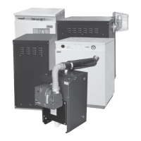
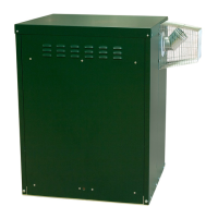
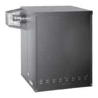
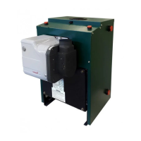
Firebird Enviromax Condensing Range
3
23
3.3 - COMBI - WIRING
Combi PCB Board
Earth. From Panel Body.
N. Mains In Plug Neutral.
L1. Mains In Plug Live.
DHW. Pump Neutral.
DHW. Pump Live.
CH. Pump Neutral.
CH. Pump Live.
Timer Permanent Live.
Timer Neutral.
DHW. Timer Switch Live.
CH.Timer Switch Live.
Room Stat 2.
Room Stat 1.
Burner Lockout.
Burner Neutral.
Burner Live.
High Limit No.2.
High Limit Comm.
High Limit No.1.
D.H.W.
C.H.
Limit.
Lock out.
Flow.
Boiler.
Tank.
19 2120
1 2 3 4 5 6 7 8 9 101112 1314 1516 1718
IMPORTANT
1. Ensure all wiring and earthing is carried out strictly to best practice and national standards.
2. Protect supply with a 5 amp fuse.
3. Use Heat Resistant Cable.
4. Route and Secure All Leads Away From Hot Parts Of This Appliance.
WARNING:
The manufacturer cannot accept responsibility for any damage to persons, animals or property due to error in
installation or in the boiler. Or due to improper or unreasonable use or non-observance of the technical instructions
enclosed with the boiler, or due to the intervention of unqualified personnel.
ELECTRICAL SUPPLY:
The boiler and controls require 230V 1 phase 50Hz electric supply protected with a 5amp fuse.
THIS APPLIANCE MUST BE EARTHED.
A qualified electrician must carry out all electric wiring in accordance with current I.E.E Regulations and any local
regulations which may apply. The mains electrical supply must be taken from a double pole isolating switch with
a 5amp fuse, positioned somewhere close to the boiler. Heat resisting cable must be used which can be routed into
the boiler through the access provided on either side of the base. Ancillary controls may be provided for with
terminal connections in the control panel.
 Loading...