D4138
Fig. 1
5
39
1
4
6
2
7
8
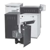
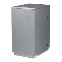
Burner Description
1 - Pump
2 - Control box
3 - RESET BUTTON WITH
LOCK-OUT LAMP
4 - Flange with insulating
gasket
5 - Air damper adjustment
screw
6 - Snorkel (BF)
7 - Pump pressure
adjustment screw
8 - Pressure gauge port
9 - Photoresistance
1.1 BURNER EQUIPMENT
Flange with insulating gasket . . . . . . . . N.º 1
Screw and nuts for flange . . . . . . . . . . . N.º 1
Hexagonal key . . . . . . .. . . . . . . . . . . . . N.º 1
Plastic air cover . . . . . . . . . . . . . . . . . . . N.º 1
Screws for flange to be fixed to boiler . . N.º 4
Flexible oil pipes with nipples . . . . . . .. . N.º 2
By-pass screw for 2 pipe system . . . . . .
N.º 1
One stage kerosene burner.
The intake air temperature must not be over 70 °C.
Burner with CE marking in conformity with EEC directives:
EMC 89/336/CEE and Efficiency 92/42/EEC.
CE Certification No.: 0036 0316/01 as 92/42/CEE.
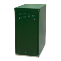
ELECTRODE SETTING
Riello RDB 2.2
ATTENTION
Before assembling or removing the nozzle
loosen screw (A) and move electrodes forward.
F i g . 4
D5912
2
3
4
7
6
5
18
H
meters
L meters
I. D.
8 mm
I. D.
10 mm
0.5
1
1.5
2
10
20
40
60
20
40
80
100
H
meters
L meters
I. D.
8 mm
I. D.
10 mm
0
0.5
1
1.5
2
3
3.5
35
30
25
20
15
8
6
100
100
100
90
70
30
20
F i g . 6
F i g . 7
H
max. 4 m
min. 0.1 m
F i g . 5
D
5741
D5740
max. 4 m
H
H
max. 4 m
H
H
D1842
WARNING
• SINGLE PIPE
The pump is designed to allow working with one pipe.
• TWO PIPE
In order to obtain two pipe working it is necessary to unscrew the
return plug (2), screw in the by-pass screw (3) and then screw in
return oil line (2). (See fig. 4).
In the two pipe systems, before starting the burner make sure that
the return pipe-line is not clogged. An excessive back pressure
would cause the damage of the pump seal.
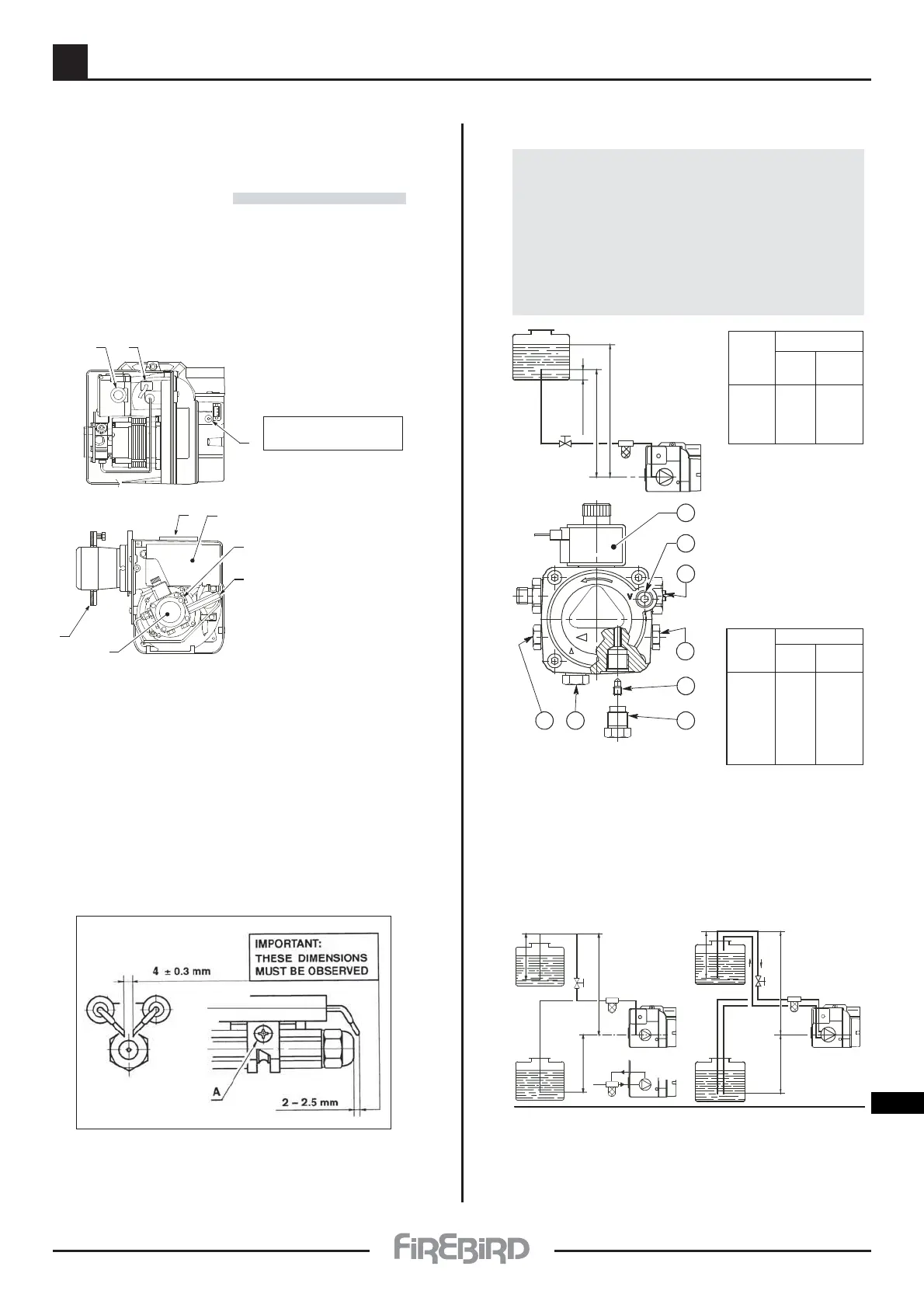
HYDRAULIC SYSTEM
1 - Suction pipe
2 - Return line
3 - By-pass screw
(* is supplied loose in burner pack )
4 - Pressure gauge connection
& Bleed screw
5 - Pressure adjuster
6 - Vacuum gauge connection
7 - Valve
8 - Auxiliary pressure test point
H = difference of level L = Max. length of the suction line
I.D. = Interminal diameter of the oil pipes
PRIMING PUMP:
On the system in fig. 5 it is sufficient to loosen the suction gauge
connection (6, fig. 4) and wait until oil flows out.
On the system s in fig. 6 and 7 start the burner and wait for the priming.
Should lock-out occur prior to the arrival of the fuel, await at least 20
seconds before repeating the operation. The pump suction should not
exceed a maximum of 0,4 bar (30 cm Hg). Beyond this limit gas is released
from the oil. Oil pipes must be completely tight.
In the vacuum systems (fig. 7) the return line should terminate within the
oil tank at the same level as the suction line. In this case a non-return valve
is not required. Should however the return line arrive over the fuel level, a
non-return valve is required. This solution however is less safe than
previous one, due to the possibility of leakage of the valve.
*
 Loading...