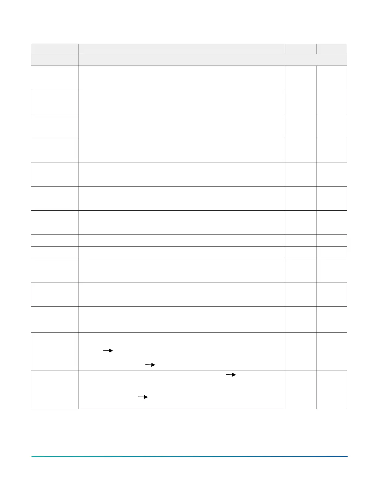
Table 63: Terminals description
TERM. Description v(V) i(A)
Main boards
+L3- RIGHT (+)Loop 3-Positive signal, right side.
(-)Loop 3-Negative signal (return), right side.
+L4- LEFT (+)Loop 4-Positive signal, left side.
(-)Loop 4-Negative signal (return), left side
+L4- RIGHT (+)Loop 4-Positive signal, right side.
(-)Loop 4-Negative signal (return), right side
+L5- LEFT (+)Loop 5-Positive signal, left side.
(-)Loop 5-Negative signal (return), left side
+L5- RIGHT (+)Loop 5-Positive signal, right side.
(-)Loop 5-Negative signal (return), right side
+L6- LEFT (+)Loop 6-Positive signal, left side.
(-)Loop 6-Negative signal (return), left side
+L6- RIGHT (+)Loop 6-Positive signal, right side.
(-)Loop 6-Negative signal (return), right side
SH Terminal for connection of the shield of cables
+RS485- SERIAL BUS. Terminals to connect the FC500 and FC500MFI modules
[M]
[24R]
24 V RESET ABLE AUXILIARY POWER SUPPLY:
Negative present on terminal [M]; Positive present on terminal [24R].
27.6 0.5(1)
[M]
[24A]
24 V AUXILIARY POWER SUPPLY:
Negative present on terminal [M]; Positive present on terminal [24A].
27.6 0.5(1)
[LE]
[LI] [-]
Terminal for connection of the external telephone line Terminal for
connection of the internal telephone line Terminal for connection of
the Earth cable
[NC]
[NO]
[C] FIRE
FIRE ALARM OUTPUT - Non-Supervised:
standby [C] connected to [NC] with [NO] open;
in the event of ALARM [C] connected to [NO] with [NC] open
[NC]
[NO]
[C] FAULT
FAULT ALARM OUTPUT - Non-Supervised: standby [C] connected
to [NC] with [NO] open
in the event of fault [C] connected to [NO] with [NC] open
FC503 and FC506 Addressable Fire Control Panels84
Johnson Controls - CONFIDENTIAL