Do you have a question about the Firepower FP-18 and is the answer not in the manual?
| Brand | Firepower |
|---|---|
| Model | FP-18 |
| Category | Welding System |
| Language | English |
Explains the meaning of "NOTE", "CAUTION", and "WARNING" used in the manual for clarity.
Covers critical safety aspects including electric shock, fire, noise, and arc rays to prevent injury and damage.
Lists relevant standards and documents for further information on safety and practices.
French terms for "note", "attention", and "warning" and their classifications.
French section detailing safety precautions for operation and maintenance.
French list of reference standards for safety and procedures.
Defines the purpose and intended audience of the service manual.
Highlights key principles for supporting equipment application and operation effectively.
Details the expected responsibilities of service technicians and customers.
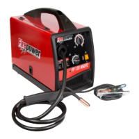
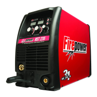
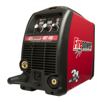
Provides detailed technical specifications for the plasma cutting system.
Introduces the section on diagnosing and isolating faulty subassemblies in the plasma cutter.
Refers to the operating manual for routine inspection and maintenance procedures.
Lists common issues encountered during plasma cutting operations and their potential causes.
Describes typical operational issues related to the compressor, power source, and torch.
Explains the methodology and format of the troubleshooting guide.
Provides general guidance and notes applicable to all repair and replacement procedures.
Step-by-step instructions for removing the unit's cover and handle for access.
Detailed procedure for replacing the torch head assembly.
Instructions for replacing only the torch switch component.
Procedure for removing and replacing the internal air compressor.
Steps for safely replacing the unit's capacitor.
Instructions for removing and installing the main control printed circuit board.
Procedure for replacing the power relay component.
Steps for replacing the main power ON/OFF switch.
Procedure for replacing the cooling fan unit.
Instructions for replacing the diode bridge rectifier.
Guide for replacing internal resistors, noting differences.
Procedure for replacing the transformer and ferrite core assembly.
Instructions for returning parts for service or warranty claims.
Lists main system configurations and torch/leads assemblies available for purchase.
Detailed itemized list of replacement parts for the power supply.
Detailed itemized list of replacement parts for the torch assembly.
Diagram illustrating the correct connections for torch leads and other wiring.
Electrical schematic detailing interconnections for Rev C units.
Electrical schematic detailing interconnections for Rev D and later units.