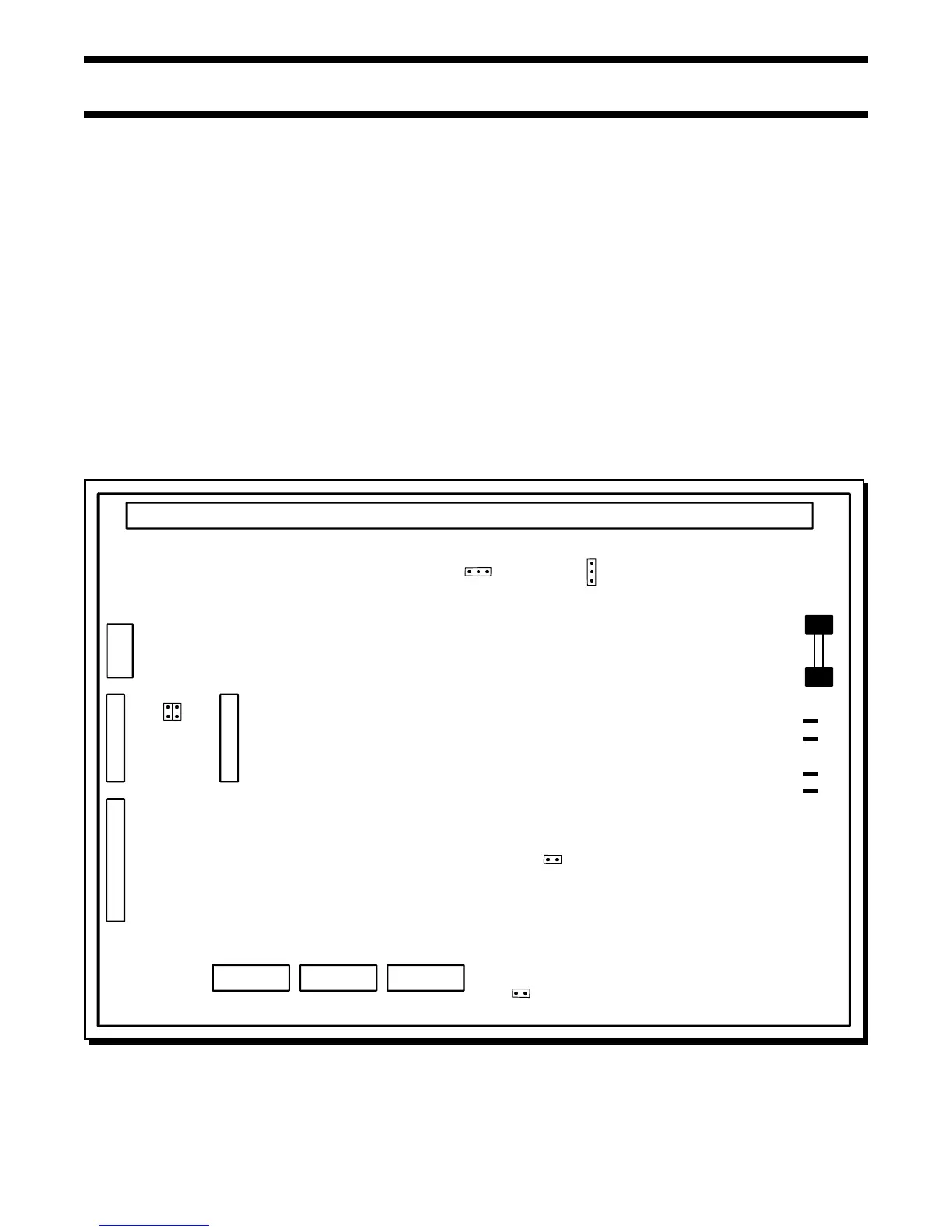
MAIN FIRE ALARM BOARD
FIELD WIRING TERMINALS
P6
F1
10 AMP
BATTERY
FUSE
SW13
1
2
3
JW2
P3
23 1
BATT+
P4
P5
P2
BATT-
XMFR
XMFR
JW1
P7
P8
JW4
JW5
JW3
JW6
SW11
SW9
P1
Page 12 of 36
Fig.5: Main Fire Alarm Module
6.0 MODULE SETTINGS
6.1 MAIN FIRE ALARM MODULE
Class A / B Selection: On the FW-C2Z, FW-C4Z and FW-C4EZ only, JW1 & JW2 are connected from 1 to 2 for Initiating Circuit Class B
(Style B) operation, and from 2 to 3 for Class A (Style D) operation. JW2 is present on the FW-C2Z. Note that
the Class A/B selection affects all Initiating Circuits, and must be used with the correct Configuration DIP
Switch Setting.
Zone Adder Module: On an FW-C4EZ only, remove the jumper on JW4 if a FW-EZM4 Zone Expansion is installed. The Zone Adder
Module is plugged into P6 & P7.
Relay Module: Remove the jumper on JW3 if an FW-RB4 or FW-RB8 Relay Module is installed. The Relay Module is plugged into
P1.
Digital Communicator: Remove the jumper on JW6 if a FW-DACT Digital Communicator is installed. The Digital Communicator is plugged
into P8.
City Tie: Remove the jumper on JW6 if a FW-RPM City Tie is installed. The City Tie is plugged into P8.
Battery: Connected to P2(+’ve) & P3(-’ve) via the factory installed cables.
Transformer: Factory wired to P4 & P5, do not disconnect.
JW5 There should be no jumper here; do not use.
SW9,11,13 Configuration DIP Switches.
Battery Fuse F1: Replace with 10 Amp, 1-1/4" Fast Acting Fuse