P1
Page 13 of 36
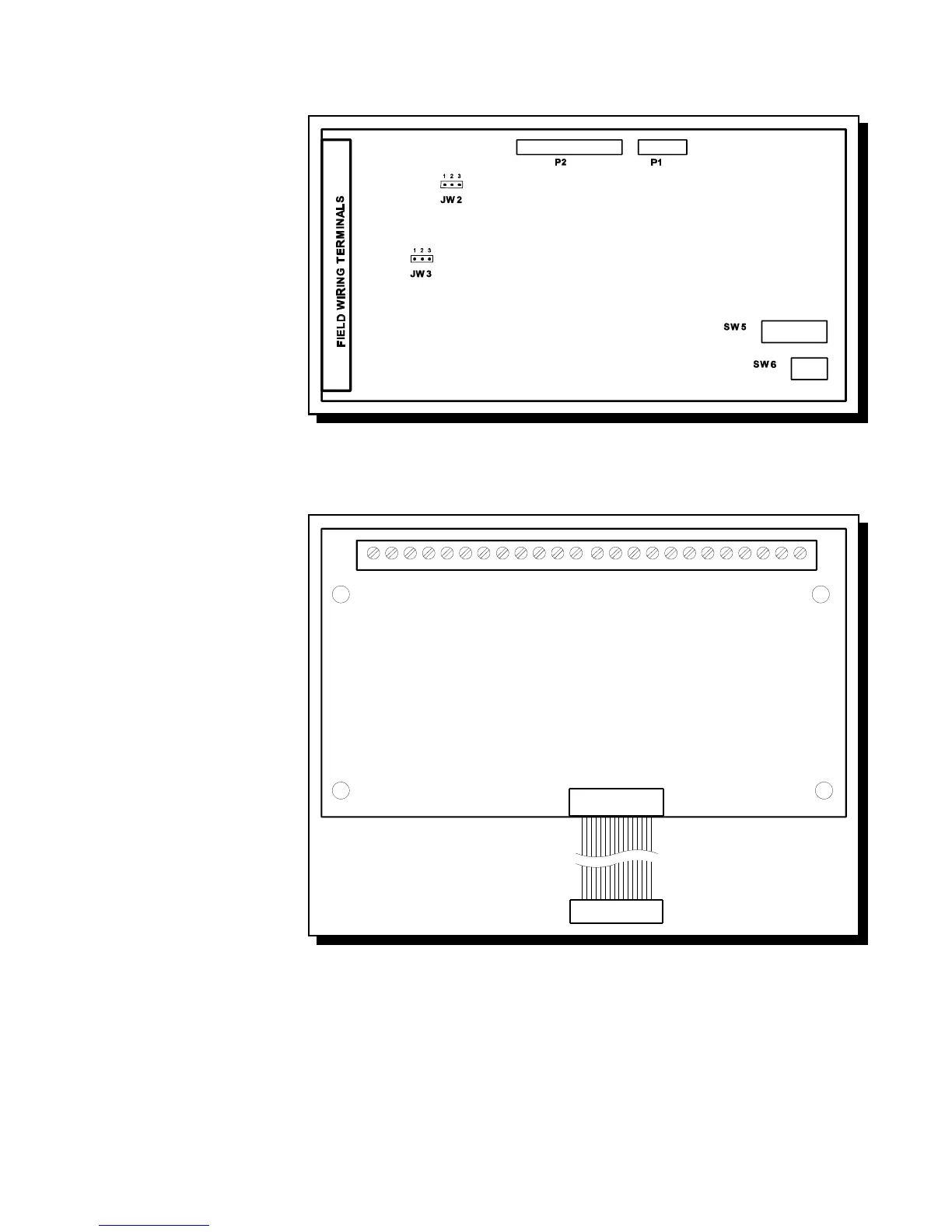
Fig.6: FW-EZM4 Zone Expansion Module
Fig.7: FW-RB4 or FW-RB8 Relay Module
6.2 ZONE EXPANSION MODULE (Model FW-EZM4)
Class A / B Selection: JW2 & JW3
are connected from 1 to 2 for Initiating
Circuit Class B (Style B) operation, and
from 2 to 3 for Class A (Style D)
operation. Note that the Class A/B
selection affects all Initiating
Circuits, and must be used with the
correct Configuration DIP Switch
Setting.
P1 & P2: Connections to P7 & P6
respectively on the Main Fire
Alarm Board.
SW5,6 Config DIP Switches.
6.3 RELAY MODULES (Models FW-RB4 or FW-RB8)
P1 Connect to P1 on the Main
Fire Alarm Board.
By the factory setting, the 4 or 8 relays
are controlled by Initiating Circuits 1 to
8 respectively. This is configured by
selecting ...
JW1 Initiating Circuit #1 controls
Relay #1.
JW2 Initiating Circuit #2 controls
Relay #2.
|
|
JW8 Initiating Circuit #8 controls
Relay #8.
Alternately, each relay may be set as
a Common Alarm or Common
Supervisory Relay by removing the
jumper from JW1 to JW1A, etc. These
jumpers have two positions to select
Alarm or Supervisory each.
JW1A Alarm or Supv. control for
Relay #1.
JW2A Alarm or Supv. control for
Relay #2.
|
|
JW8A Alarm or Supv. control for Relay #8.
Finally, there are jumpers JW1.2, JW2.3, up to JW7.8 that allow a relay to have the same control as an adjacent relay. For example, starting with
the factory default setting, moving the jumper from JW2 to JW1.2 will make both Relays 1 & 2 operate with Initiating Circuit #1.