Page 29 of 36
On the FW-EZM4 Zone Expansion Module ...
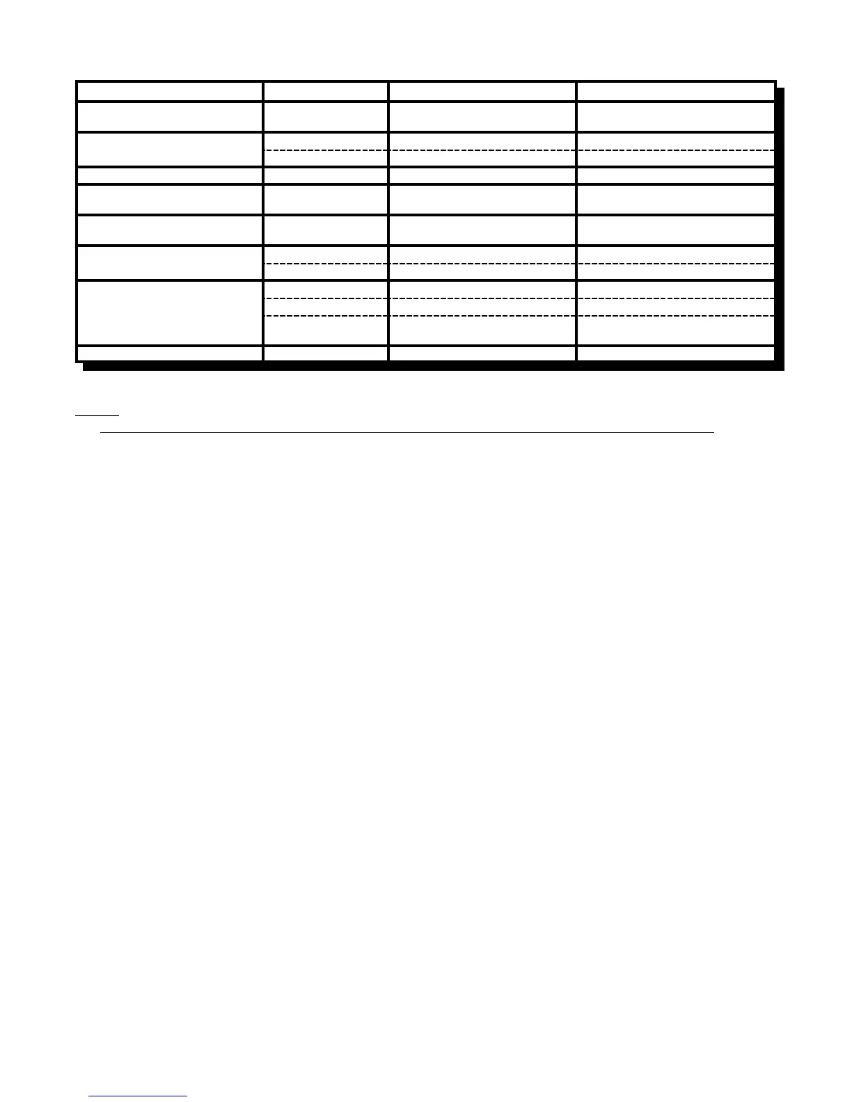
Function DIP Switch Switch “Off” Switch “On”
Indicating Circuit #3
Audible Device (Bell) Only
Switch 6, #1 Silenceable Non-Silenceable
Indicating Circuit #4
Audible or Visual Device
Switch 6, #2 Silenceable Non-Silenceable
Switch 6, #3 Audible Device (Bell) Visual Device (Strobe)
Not Used Switch 6, #4 ----------------- -----------------
Initiating Circuit #5
Alarm Only
Switch 5, #1 Normal Alarm Verified Alarm
Initiating Circuit #6
Alarm Only
Switch 5, #2 Normal Alarm Verified Alarm
Initiating Circuit #7
Alarm or Waterflow
Switch 5, #3 Normal Verified Alarm / Retarded Waterflow
Switch 5, #4 Alarm Waterflow
Initiating Circuit #8 Switch 5, #6 Alarm Supervisory
Alarm or Supervisory
Switch 5, #5 Normal Verified Alarm (no effect on Supv.)
Switch 5, #7
Non-Latching Supervisory Latching Supervisory
(No effect on Alarm) (No effect on Alarm)
Not Used Switch 5, #8 ----------------- -----------------
Notes:
& After any Configuration Switches are changed, it is necessary to perform a System Reset !!
& Only Indicating Circuit 4 may be configured for Visual Devices.
& If Initiating Circuit 7 is configured as Waterflow, the corresponding Verified selection becomes a Retard selection.
Note: Do not use Retard Operation with any external Retarding device; maximum Retard may not exceed 120 seconds.
& If Initiating Circuit 8 is configured as Alarm, the corresponding Latching selection has no effect.
& If Initiating Circuit 8 is configured as Supervisory, the corresponding Verified selection has no effect.
& The selection of Class A/B (Style Z/Y) Notification Circuits is only a matter of how they are wired. See Connection
Info.
& If Class A (Style D) Initiating Circuits are selected the appropriate Board Jumpers must also be set. Class B
Initiating Circuits 5&6 combine to create Class A Circuit #3, and Class B Initiating Circuits 7&8 combine to create
Class A Circuit #4. DIP Switches for Circuits 5 to 8 are ignored, and LED Indicators for Circuits 5 to 8 are non-
functional.